Method of Switching Functions of a Device without Attaching and Detaching the Device

a technology of switching functions and devices, which is applied in the field of method of switching functions of devices without attaching and detaching devices, can solve the problems of high fabrication cost of such conventional techniques, inconvenient use, and inability to meet the needs of common users,

a technology of switching functions and devices, which is applied in the field of method of switching functions of devices without attaching and detaching devices, can solve the problems of high fabrication cost of such conventional techniques, inconvenient use, and inability to meet the needs of common users,

US20090217304A1Inactive Publication Date: 2009-08-27ALICORP

Image

  • Method of Switching Functions of a Device without Attaching and Detaching the Device
  • Method of Switching Functions of a Device without Attaching and Detaching the Device
  • Method of Switching Functions of a Device without Attaching and Detaching the Device

Examples


Embodiment Construction

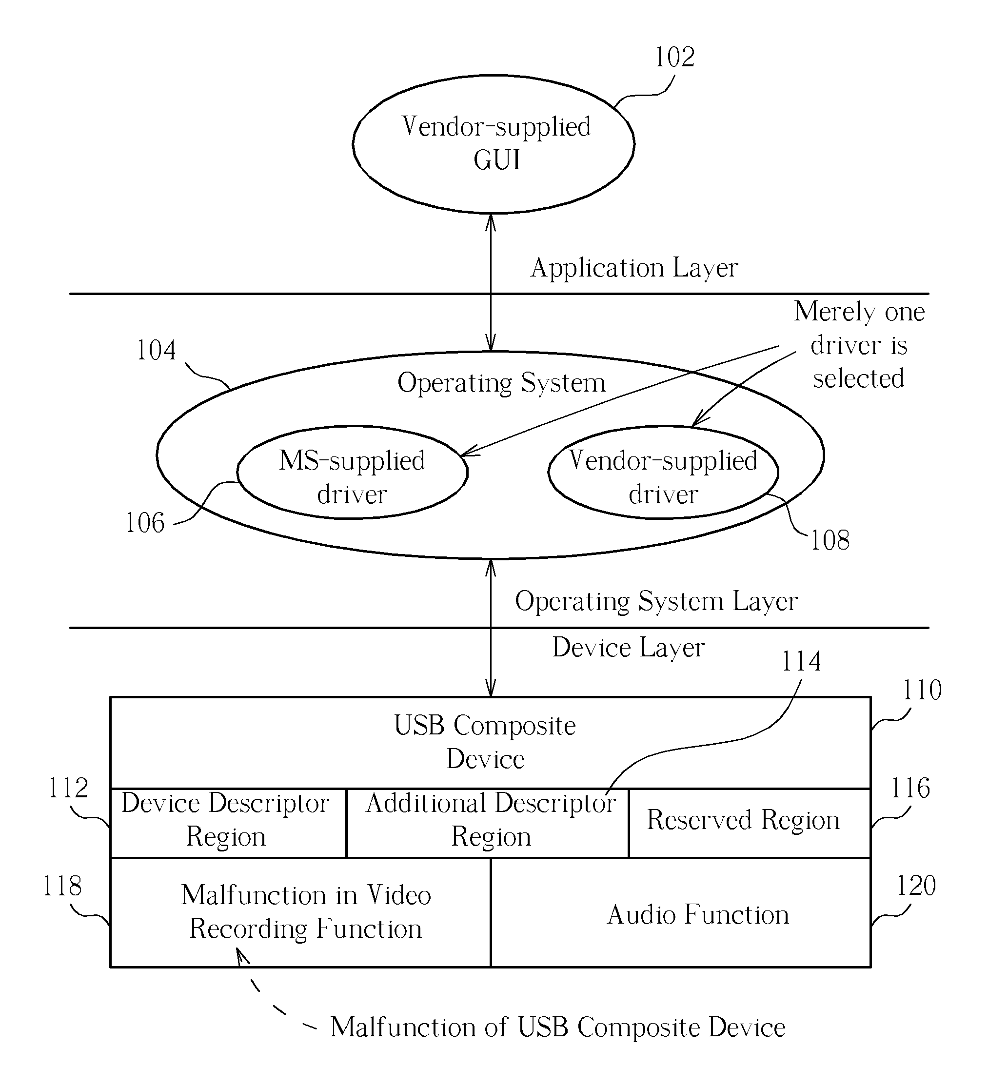
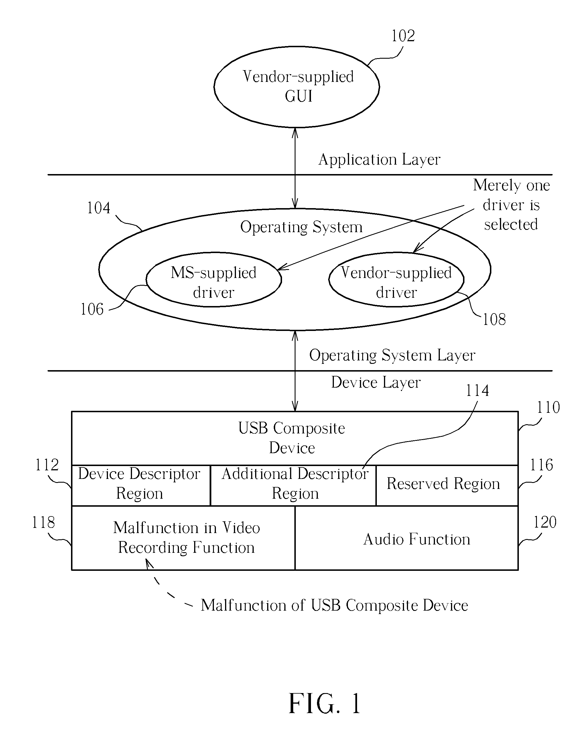
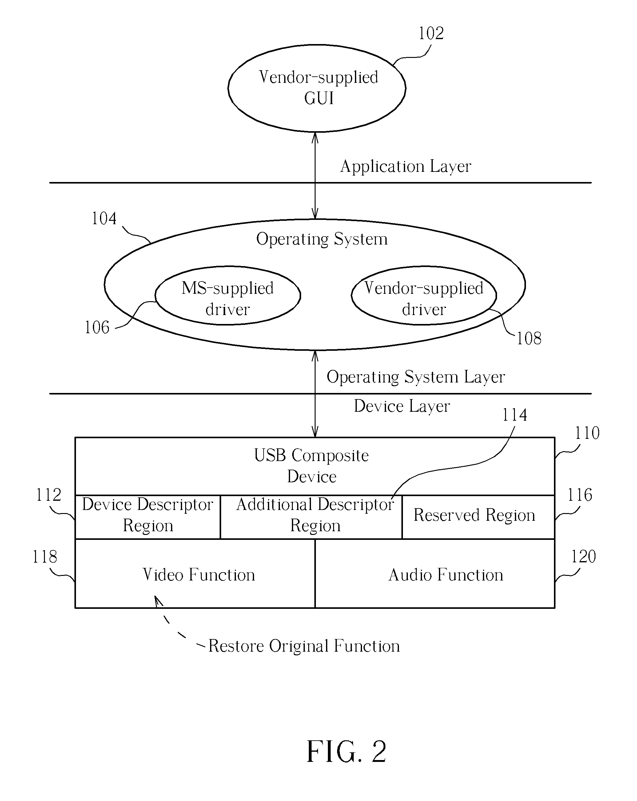
[0015]For neutralizing defects including high fabrication costs and the at least one cycle of detaching and attaching the peripheral device, a method of switching functions of a device without attaching and detaching the device is disclosed in the present invention. Characteristics of the disclosed method include correlating different functions of the peripheral device (or switching different combinations of the functions) to at least one VID / PID in the device descriptor of the peripheral device, and switching the correlated functions (or switching correlated combinations of the functions) of the peripheral device by switching different VID / PIDs.

[0016]Please refer to FIG. 3, which is a flowchart of the disclosed method of switching functions of a device without attaching and detaching the device in the present invention, where the disclosed method is applied in a peripheral device attached to the USB. As shown in FIG. 3, the disclosed method of switching functions of the device incl...


PUM


Abstract

According to different VID / PIDs stored in a device descriptor of a USB composite device, various functions and corresponding drivers are assigned and switched. Therefore, the switches of functions are achieved without detaching and attaching the USB composite device. Possible problems while switching operation systems of different platforms are overcome. And the high cost in embedding various drivers into a mainframe is reduced.

Description

BACKGROUND OF THE INVENTION[0001]1. Field of the Invention[0002]The present invention relates to a method of switching functions of a device, and more particularly, to a method of switching functions of a device without attaching and detaching the device.[0003]2. Description of the Prior Art[0004]In Universal Serial Bus (USB) specifications, each peripheral device connected to the USB acquires an endpoint address, and communications between a mainframe and an endpoint are established through virtual pipes. Therefore, after a virtual pipe has been established, each endpoint returns a descriptor to both the USB and the mainframe (or an operating system of the mainframe) so that the mainframe perceives information related to each peripheral device. Information carried in the descriptor and related to a corresponding peripheral device includes class properties, a transmission category, a maximum package size, and a bandwidth.[0005]For describing different types of data, different types ...

Claims


Application Information

Patent Timeline
27 Aug 2009
Publication
US20090217304A1
IPC
G06F9/44
CPC
G06F9/4411
Inventors
SHIH, PO-CHUAN; HSU, CHEN-PANG