View point detecting device

a technology of detecting device and gaze point, which is applied in the field of can solve the problems of reducing convenience for users and difficulty in precisely detecting the conventional line of sight detecting device described above, and achieve the effect of improving the accuracy of gaze point detection and maintaining convenience for users

Inactive Publication Date: 2009-09-03
NAT UNIV CORP SHIZUOKA UNIV
View PDF4 Cites 40 Cited by
  • Summary
  • Abstract
  • Description
  • Claims
  • Application Information

AI Technical Summary

Benefits of technology

[0009]According to a gaze point detecting device of the present invention, it is possible to improve the precision in detection of the gaze point of the object person to a display image while maintaining convenience for a user.

Problems solved by technology

However, it is difficult for the conventional line of sight detecting devices described above to precisely detect a line of sight or a gaze point to an object to be observed, such as a display, when the position of an object person relative to the device changes due to a deviation of a mounting position.
However, frequent calibrating operations due to mounting deviations reduce the convenience for a user.

Method used


Image

  • View point detecting device
  • View point detecting device
  • View point detecting device

Examples


Embodiment Construction

[0035]A preferred embodiment of a gaze point detecting device of the present invention will be described in detail below with reference to the accompanying drawings. In the description of the drawings, portions that are the same or equivalent are denoted by the same numerals, and duplicated descriptions thereof will be omitted. Each drawing is prepared for illustration and is shown so as to particularly emphasize object portions for illustration. For that reason, the dimension ratio of each member in the drawings does not necessary correspond to the actual ratio.

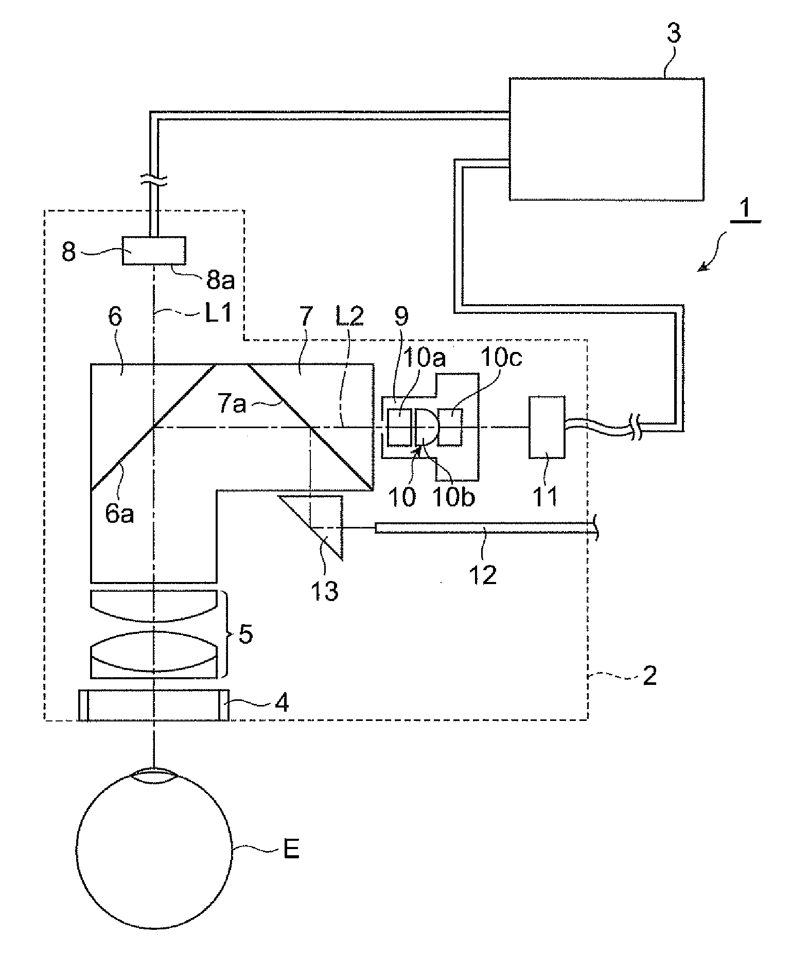
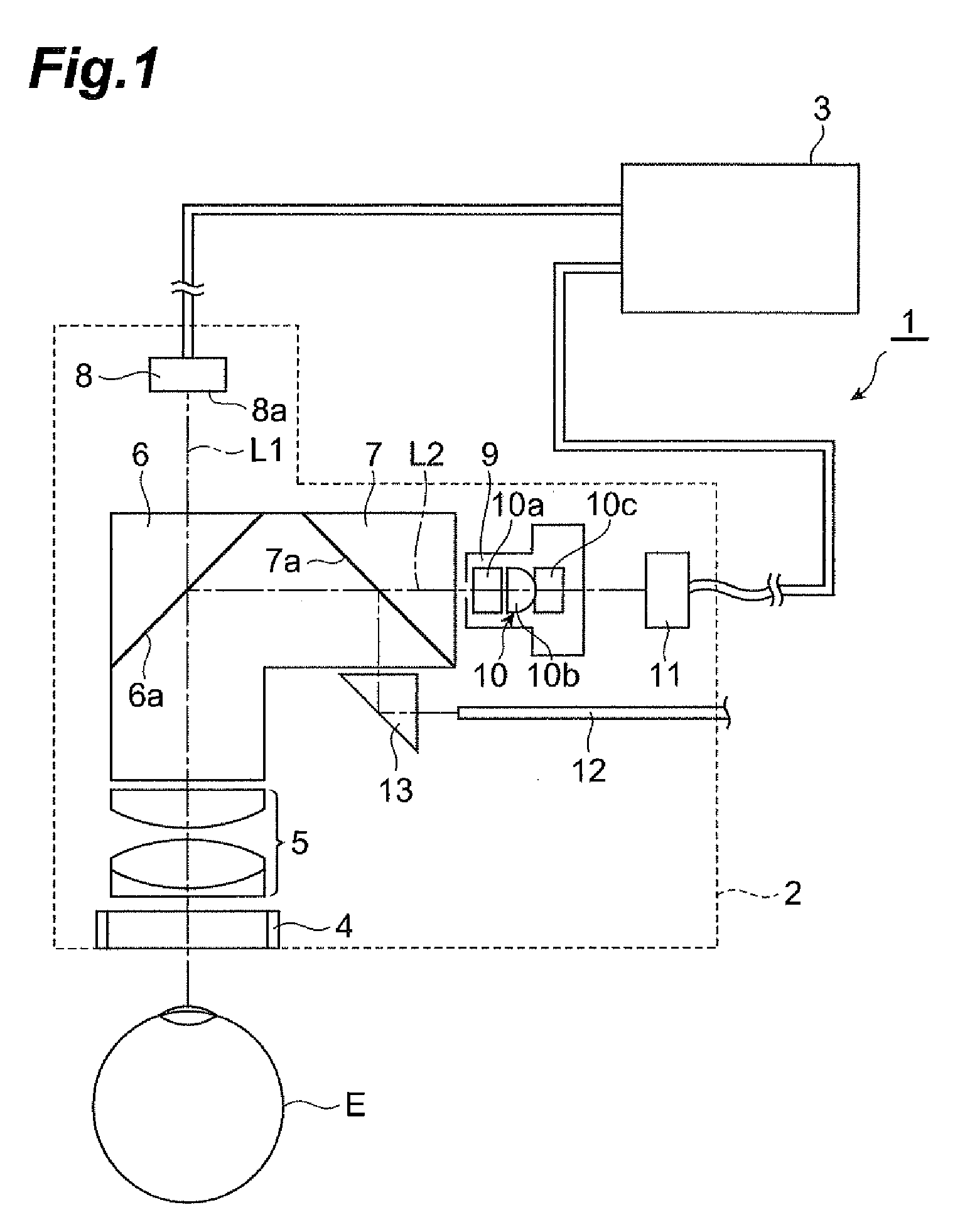
[0036]FIG. 1 is a portion of a cross sectional configuration diagram illustrating a schematic configuration of gaze point detecting device 1 of one preferred embodiment of the present invention. As illustrated in FIG. 1, the gaze point detecting device 1 includes a head mount display 2 (hereinafter, called an HMD) mounted on the head of a object person for detecting a line of sight, a personal computer connected to the HMD 2...


PUM


Abstract

A gaze point detecting device 1 detects a gaze point of an object person by projecting a display image displayed by an LCD 8 to outside via a finder 4 and capturing an eye image of the object person by a CCD 11 in response to illumination light irradiated toward outside from the finder 4, and the device comprises an optical system 5 arranged spaced only a focal length apart from a display surface 8a on an optical path of an image displaying optical system between the LCD 8 and the finder 4; the optical system 5 being arranged on an optical path of an imaging optical system between the finder 4 and the CCD 11; a telecentric optical system including a diaphragm 9 arranged spaced only a focal length apart from the optical system 5 on the optical path; and a controller 3 that detects a position of the gaze point of the object person based on the eye image captured by the CCD 11.

Description

TECHNICAL FIELD[0001]The present invention relates to a line of sight detecting device that detects a gaze point of an object person to an image displayed.BACKGROUND ART[0002]There has been conventionally known a device that detects a line of sight direction or a gaze point of an object person on an object to be observed, such as a display. For example, in a non-patent document 1 described below, there is described a device that measures which portion in a display screen an object person gazes at by placing a camera at a distance 50 to 80 cm from a face of the object person. Also, there is known a pointing device that detects a pupil from a face image using a camera and moves a cursor on a display screen in response to a movement of the pupil caused by a movement of the head of the object person (refer to the patent document 1 below).[0003]On another front, a head mount display type line of sight detecting device (hereinafter, called HMD) capable of responding to large movements of ...

Claims


Application Information

Patent Timeline
Patent Type & Authority Applications(United States)
IPC IPC(8): A61B3/113G06F3/0346
CPCG06F3/013A61B3/113
Inventor EBISAWA, YOSHINOBU
Owner NAT UNIV CORP SHIZUOKA UNIV
Why Eureka
Try Eureka