Imaging apparatus

a technology of imaging apparatus and touch panel, which is applied in the direction of electric apparatus casing/cabinet/drawer, printer, instrument, etc., can solve the problems of deteriorating the visibility of the the width of the imaging apparatus is too small for a user to firmly hold the imaging apparatus with both hands, and the inability to firmly hold the imaging apparatus, etc., to achieve the effect of maintaining the visibility of the display screen and the operability of the touch panel

a technology of imaging apparatus and touch panel, which is applied in the direction of electric apparatus casing/cabinet/drawer, printer, instrument, etc., can solve the problems of deteriorating the visibility of the the width of the imaging apparatus is too small for a user to firmly hold the imaging apparatus with both hands, and the inability to firmly hold the imaging apparatus, etc., to achieve the effect of maintaining the visibility of the display screen and the operability of the touch panel

US20090224999A1Active Publication Date: 2009-09-10NINTENDO CO LTD

Image

  • Imaging apparatus
  • Imaging apparatus
  • Imaging apparatus

Examples


Embodiment Construction

Configuration of Imaging Apparatus

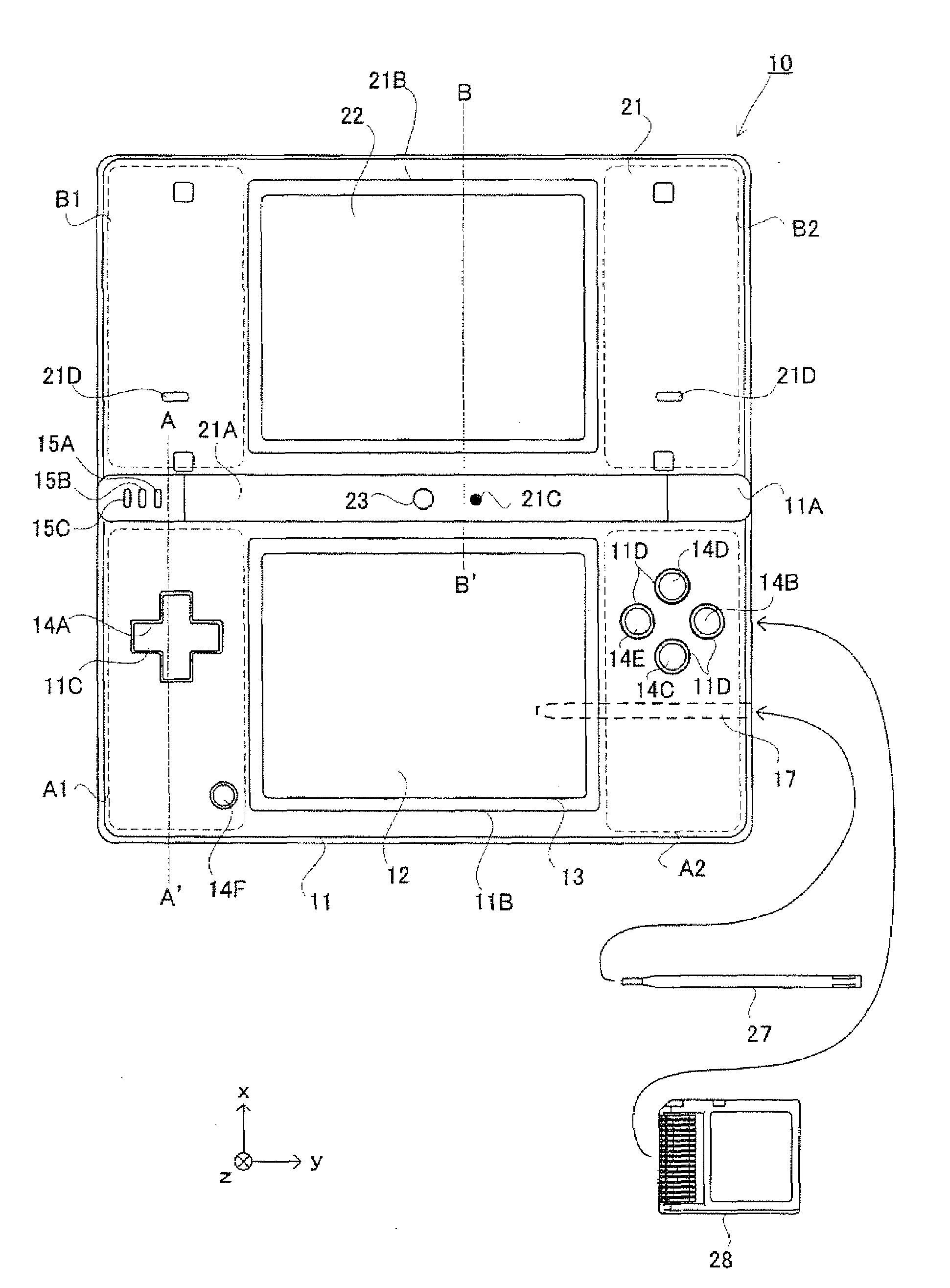
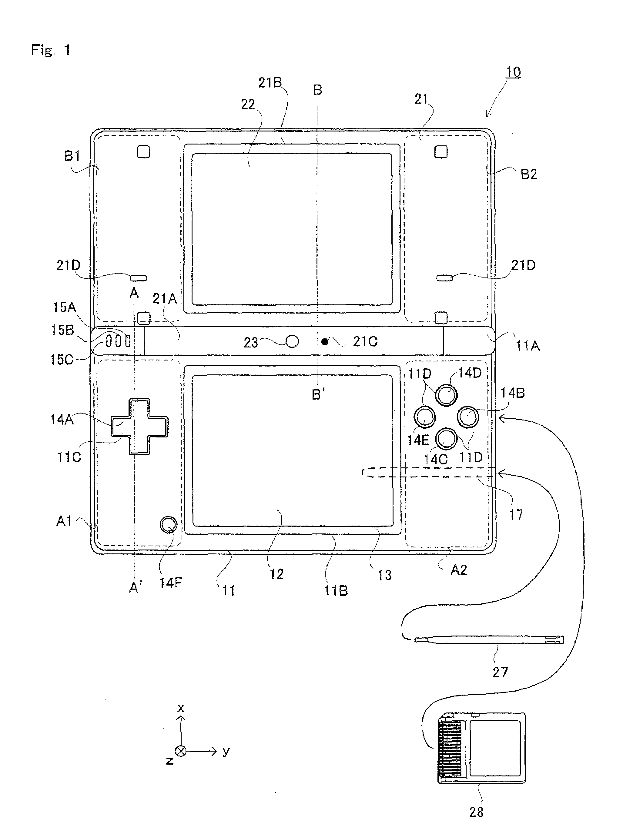
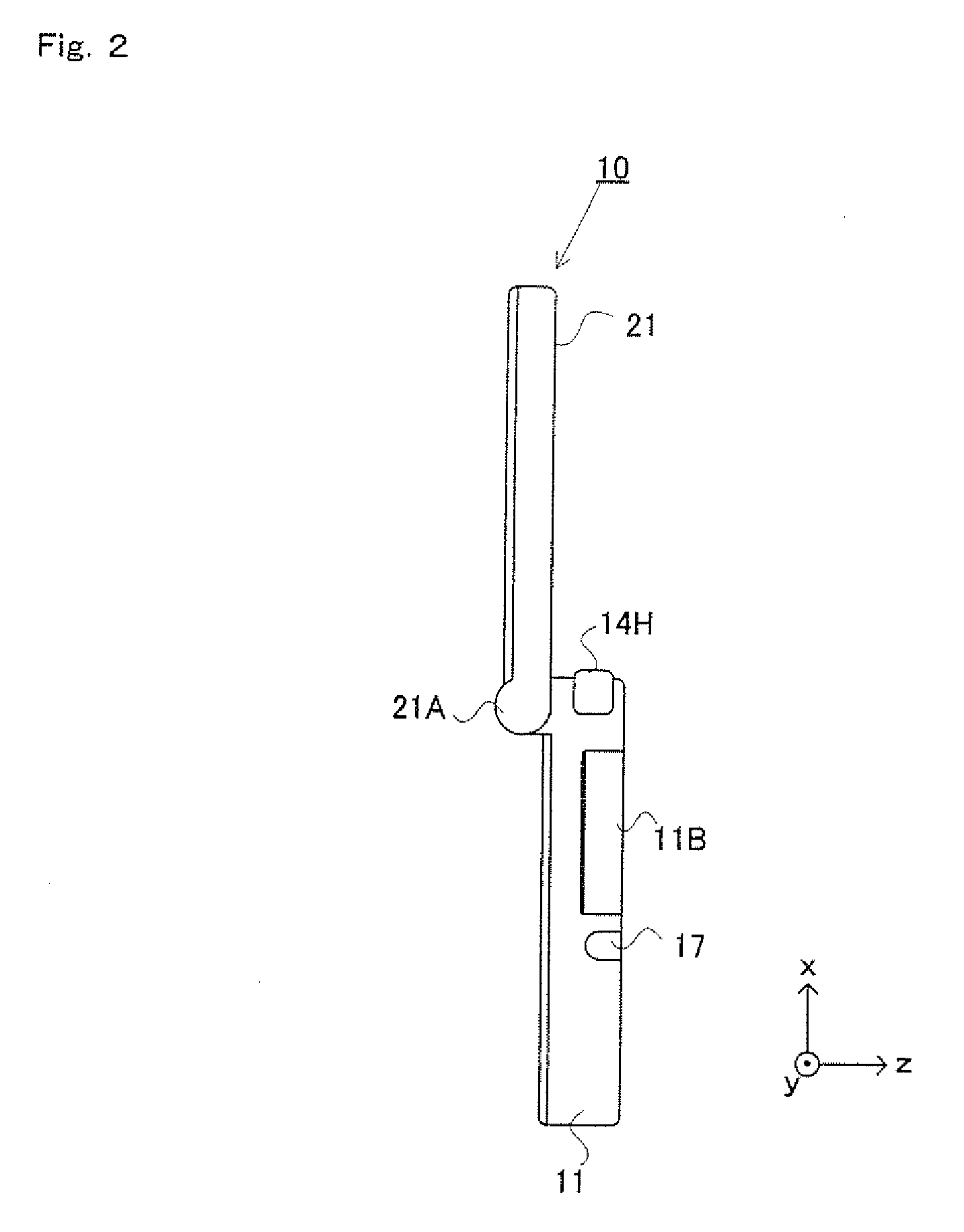
[0061]The following will describe an imaging apparatus according to an embodiment of the present invention. FIGS. 1 to 3 are external plan views of the imaging apparatus 10. The imaging apparatus 10 is a foldable imaging apparatus, FIGS. 1 and 2 show the imaging apparatus 10 in an opened state, and FIGS. 3A to 3D show the imaging apparatus 10 in a closed state. More specifically, FIG. 1 is a front view of the imaging apparatus 10 in the opened state, and FIG. 2 is a side view of the imaging apparatus in the opened state. The imaging apparatus 10 takes an image with a camera, displays the taken image on a screen, and stores data of the taken image. The imaging apparatus 10 includes two display devices (LCDs 12 and 22) and two cameras (cameras 23 and 25).

[0062]FIGS. 15 to 17 are external plan views of an imaging apparatus according to a modified example of the present embodiment. FIG. 15 is a front view of the imaging apparatus 10 in an opened state, ...


PUM


Abstract

An imaging apparatus 10 includes a lower housing 11, an upper housing 21, a lower LCD 12, an outer camera, a plurality of buttons 14A to 14E, and a touch panel 13. The lower housing 11 has a horizontally long shape. The upper housing 21 has a horizontally long shape, and a long side of the upper housing 21 is connected to an upper long side of the lower housing 11 such that the lower housing 11 and the upper housing 21 are foldable. The lower LCD 12 has a display screen which is provided in an inner surface of the lower housing 11. The outer camera is provided in an outer surface of the upper housing 21, and located at an end of the outer surface of the upper housing 21 which is opposite to a connection portion where the upper housing 21 is connected to the lower housing 11. The plurality of buttons 14A to 14E are provided on an inner surface of the lower housing 11 and on both sides of the display screen in a horizontal direction of the lower housing 11. The touch panel 13 is provided on the display screen.

Description

CROSS REFERENCE TO RELATED APPLICATIONS[0001]This application is a divisional of U.S. application Ser. No. 12 / 149,461 filed May 1, 2008 which in turn claims priority of Japanese Application No. 2008-109032 filed Apr. 28, 2008, the disclosures of both of which are incorporated herein by reference in their entirety.BACKGROUND OF THE INVENTION[0002]1. Field of the Invention[0003]The present invention relates to an imaging apparatus, and more particularly to an imaging apparatus which is held and used by a user when taking an image.[0004]2. Description of the Background Art[0005]Conventionally, there exists an imaging apparatus which takes an image with a camera and displays the taken image on a display device. For example, Patent Document 1 (Japanese Laid-Open Patent Publication No. 2006-311224) discloses an imaging apparatus which is a foldable mobile phone having an imaging function. The imaging apparatus includes two vertically long housings which are connected to each other at shor...

Claims


Application Information

Patent Timeline
10 Sep 2009
Publication
US20090224999A1
IPC
G09G5/00
CPC
A63F13/00; A63F2300/1068; H04N5/2251; A63F2300/301; A63F2300/695; A63F2300/1093; H04N23/531; H04N23/631
Inventors
KUWAHARA; KOSHIISHI, KAZUNORI