Fuel cell power supply device

a fuel cell and power supply device technology, applied in battery/fuel cell control arrangement, secondary cell servicing/maintenance, dynamo-electric converter control, etc., can solve the problems of difficult downsizing of fuel cell power supply devices, large volume of storage means,

Inactive Publication Date: 2010-04-29
HONDA MOTOR CO LTD
View PDF9 Cites 9 Cited by
  • Summary
  • Abstract
  • Description
  • Claims
  • Application Information

AI Technical Summary

Benefits of technology

[0032]According to the present invention, it is possible to carry out electric power output and

Problems solved by technology

Further, in order to secure the driving electric power to a high-power driving motor, it is necessary to increase the capacity of the storage means which assists the output electricity of the fuel cell,

Method used


Image

  • Fuel cell power supply device
  • Fuel cell power supply device
  • Fuel cell power supply device

Examples


first embodiment

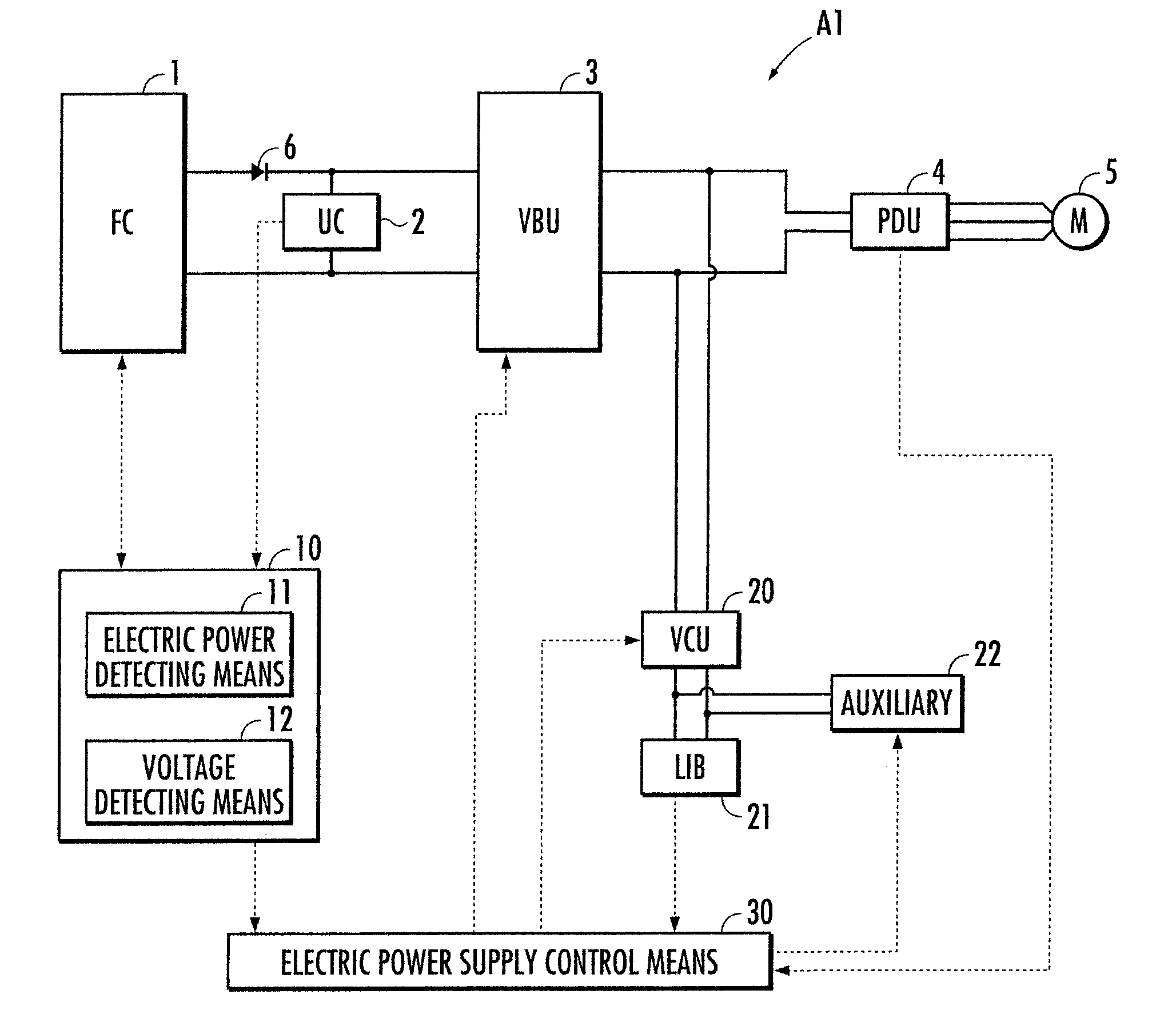
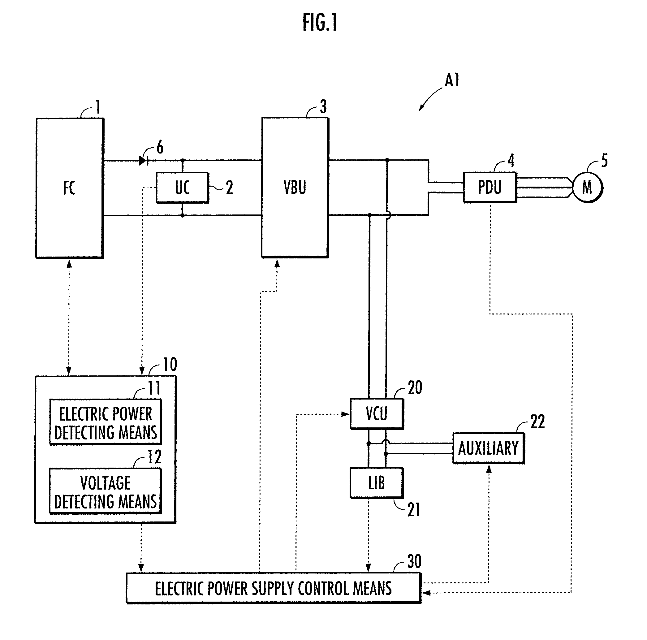
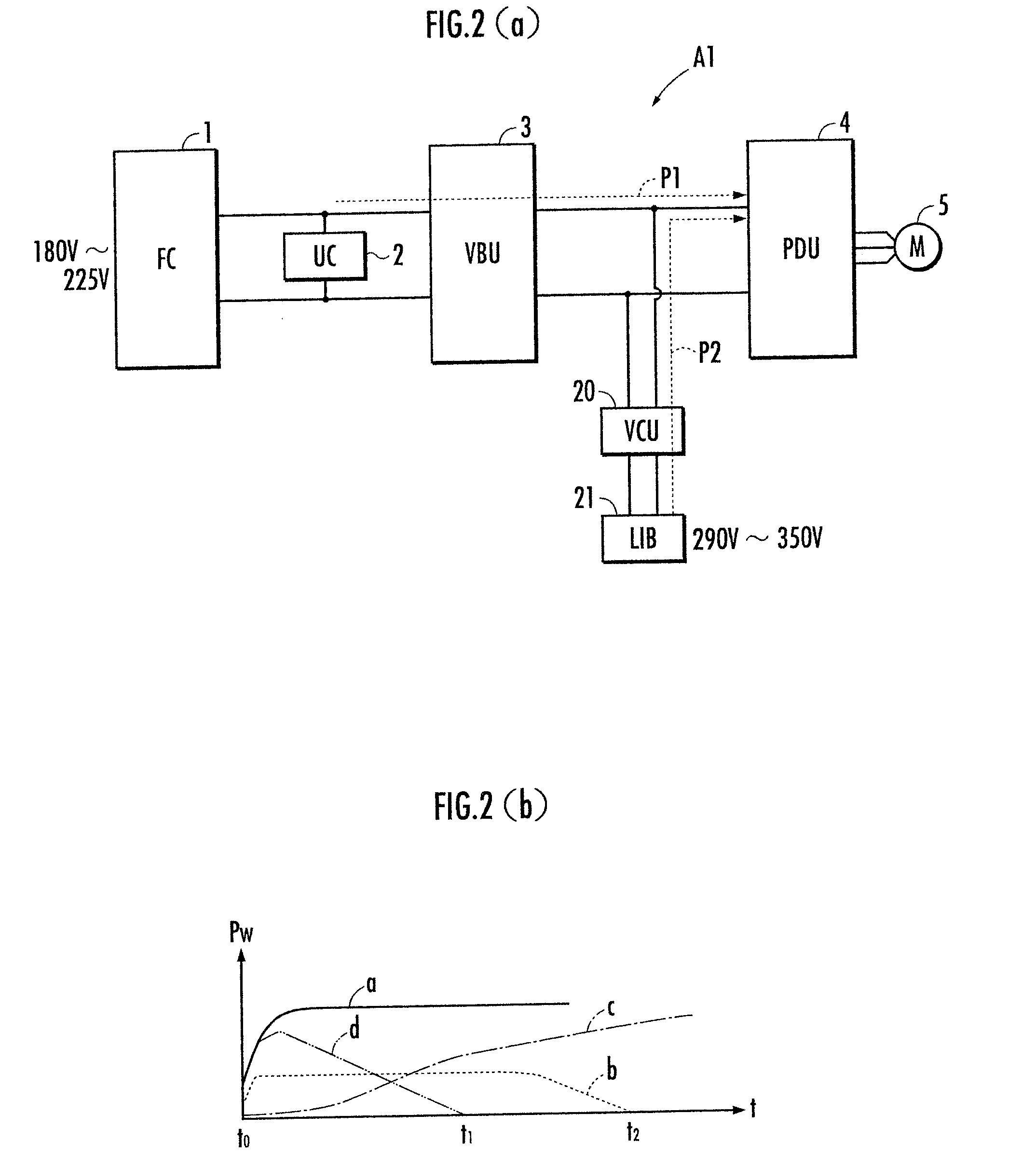
[0040]With reference to FIG. 1 through FIG. 5, a first embodiment of the present invention will now be explained below. FIG. 1 shows an overall configuration of a fuel cell power supply device according to a first embodiment of the present invention, FIG. 2 illustrates how electric power is supplied by the fuel cell power supply device shown in FIG. 1, FIG. 3 and FIG. 4 illustrate how electric power is supplied in accordance with the running condition of the fuel cell automobile, and FIG. 5 illustrates how the regenerative electric power is recovered in accordance with the running condition of the fuel cell automobile.

[0041]With reference to FIG. 1, a fuel cell power supply device A1 of the first embodiment is mounted on a fuel cell vehicle (corresponding to a vehicle of the present invention), and includes: a fuel cell 1; an electrical double layer capacitor 2 (corresponding to a storage means of the present invention, and hereinafter simply referred to as the capacitor 2) connecte...

second embodiment

[0067]Next, with reference to FIG. 6(a), an explanation will be given on a second embodiment of the present invention. A fuel cell power supply device A2 of the second embodiment is a device in which the capacitor 2 of the fuel cell power supply device A1 mentioned in the first embodiment explained above is substituted by a secondary battery 50 (corresponds to the storage means of the present invention; a lithium ion battery is used in the second embodiment). Here, the configurations which are the same as the fuel cell power supply device A1 in the first embodiment are denoted by the same reference numerals and explanation thereof is omitted.

[0068]The fuel cell power supply device A2 of the second embodiment is capable of obtaining the same effect as the fuel cell power supply device A1 of the first embodiment mentioned above. The secondary battery 50 is, for example, when the operating voltage range of the fuel cell 1 is in the range of from about 180 V to about 225 V, configured b...

third embodiment

[0071]Next, with reference to FIG. 6(b), an explanation will be given on a third embodiment of the present invention. The fuel cell power supply device A3 of the third embodiment is the device in which a capacitor 50 of the fuel cell power supply device A1 mentioned in the first embodiment explained above is substituted by a secondary battery 60 (corresponds to the storage means of the present invention; a lithium ion battery is used in the third embodiment) which is connected in parallel to the output unit of the voltage boosting means 3. Here, the configurations which are the same as the fuel cell power supply device A1 in the first embodiment are denoted by the same reference numerals and explanation thereof is omitted.

[0072]Further, a contactor 61 is provided between the voltage boosting means 3 and the PDU 4 and the secondary battery 60, and a high-voltage auxiliary 62 (the auxiliary which operates with supply of high voltage, and includes the auxiliary of the fuel cell 1; corr...


PUM


Abstract

A fuel cell power supply device can include a fuel cell, a voltage boosting device with an input unit connected to the fuel cell, and an output unit connected to a first load. The boosting device can boost an output voltage and supply electric power to the first load. A storage device is connected to the input unit or the output unit, and a secondary battery can be connected to the output unit of the voltage boosting device via a voltage conversion device. An electric power supply control device controls operation of the voltage conversation device, to carry out supply of electric power to the first load from the secondary battery via the voltage conversion unit. The electric power supply control device also carries out charging of the secondary battery by the supply of electric power to the secondary battery from the voltage boosting device via the voltage conversion device.

Description

BACKGROUND OF THE INVENTION[0001]1. Technical Field[0002]The present invention relates to a fuel cell power supply device which supplies electric power to a load from a parallel circuit of a fuel cell and a capacitor.[0003]2. Description of the Related Art[0004]Conventionally, as a power source for a fuel cell vehicle, there is known a fuel cell power supply device in which, for example, a fuel cell and a storage means (a capacitor, a secondary battery and the like) are connected in parallel to a driving motor, so as to supply electric power to the driving motor from the fuel cell and the storage means (for example, refer to Japanese Patent Application Laid-Open No. 2006-59685 (Pages 4-5, FIG. 1)).[0005]In such conventional fuel cell power supply device, output units of the fuel cell and the storage means are directly connected to the driving motor. Further, because the output voltage per 1 cell of the fuel cell is low, it is necessary to configure a fuel cell stack in which a large...

Claims


Application Information

Patent Timeline
IPC IPC(8): H01M8/04
CPCB60L11/1887B60L11/1892H01M8/04544H01M8/04604H01M8/04925H01M10/44Y02E60/50H01M2250/20H02P2201/09Y02T10/642Y02T90/32Y02T90/34H01M16/006H02J7/345B60L58/40B60L58/33H02J2300/30Y02T10/64Y02T90/40Y02T10/70Y02E60/10
Inventor HIRAKAWA, MITSUAKIFUJINO, TAKESHINOGUCHI, MINORUKOMAZAWA, EISUKE
Owner HONDA MOTOR CO LTD
Why Eureka
Try Eureka