Hollow fiber membrane dehumidifier

a technology of hollow fiber membrane and dehumidifier, which is applied in the direction of membranes, nuclear engineering, separation processes, etc., can solve the problems of difficult placement of hollow fiber membrane modules, difficult concentrically arranging, and many problems of hollow fiber membrane dehumidifiers

Inactive Publication Date: 2010-05-06
KK TOSHIBA
View PDF8 Cites 6 Cited by
  • Summary
  • Abstract
  • Description
  • Claims
  • Application Information

AI Technical Summary

Benefits of technology

[0021]According to the present invention, there is provided a hollow fiber membrane dehumidifier comprising: a dehumidification container including a first trunk provided with exhaust gas outlet sections and a second trunk provided with exhaust gas inlet sections; a first tube plate for forming an exhaust gas outlet chamber at a side of the first trunk; a partition plate arranged in the dehumidification container to partition inside of the dehumidification container into an exhaust gas processing chamber including purge gas flow out sections and a purge gas chamber includ

Problems solved by technology

Therefore, there is a problem that it is difficult to put a hollow fiber membrane module 1 into the trunk body 6 and place it in position without allowing the third seal member 18 and the fourth seal member 19 to fall down because they are not rigidly secured to the hollow fiber membrane module 1.
In other words, the hollow fiber membrane dehumidifier has many problems from the viewpoint of assembly and sealing.
Thus, there is a problem that each of the hollow fiber membrane modules 1 occupies a large area to make the body trunk 6 large because of the outer diameter of the cap 15.
Additionally, each hollow fiber membrane module 1 has a long

Method used


Image

  • Hollow fiber membrane dehumidifier
  • Hollow fiber membrane dehumidifier
  • Hollow fiber membrane dehumidifier

Examples


Embodiment Construction

[0034]Now, the present invention will be described in greater detail with reference to the accompanying drawings that illustrate preferred embodiments of hollow fiber membrane dehumidifier according to the present invention. Throughout the following description and in the drawings, same or similar parts are denoted by the same reference symbols and will not be described repeatedly.

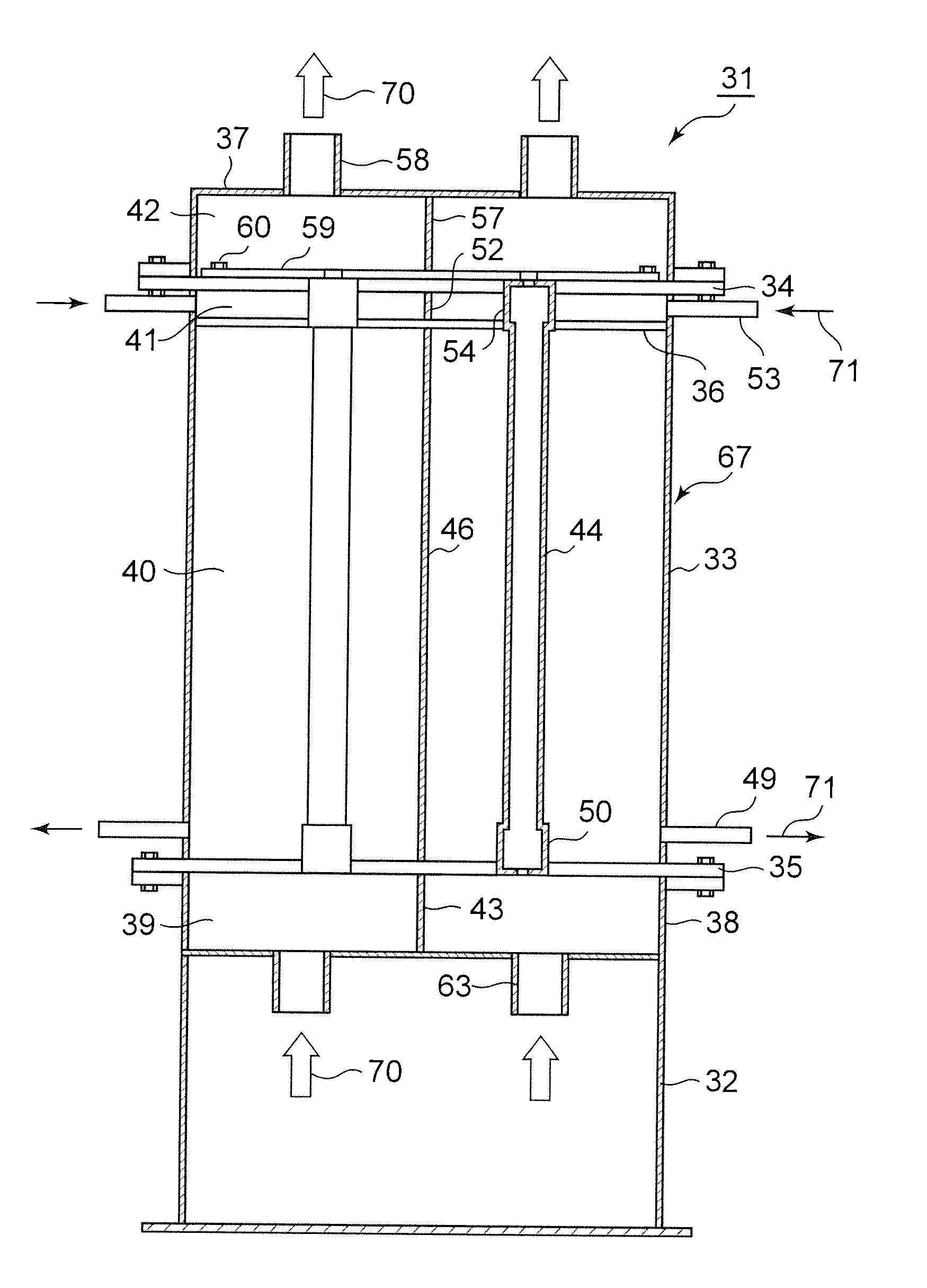
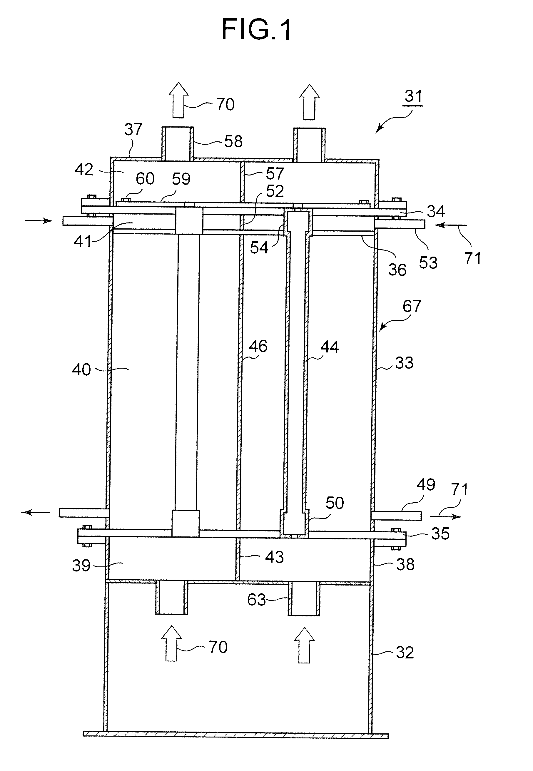
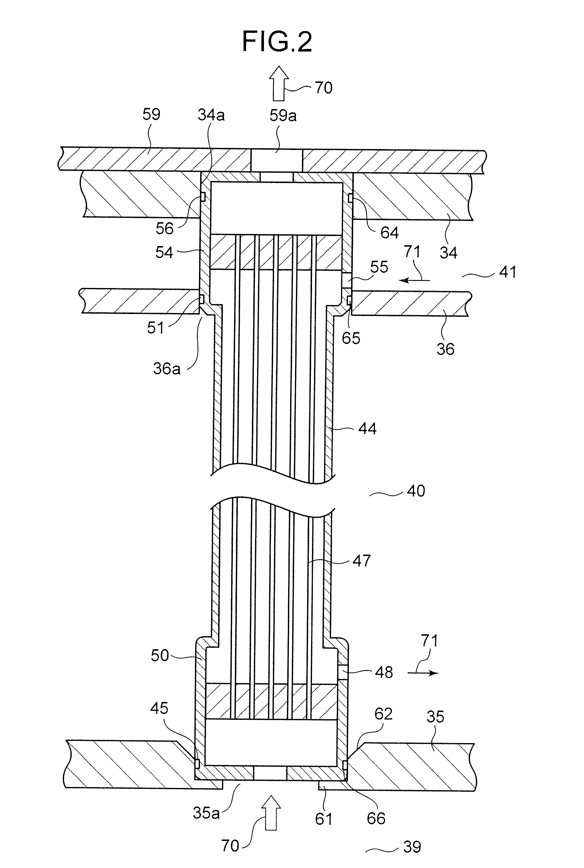
[0035]FIG. 1 is a schematic longitudinal cross-sectional view of an embodiment of hollow fiber membrane dehumidifier according to the present invention, showing the structure thereof. FIG. 2 is an enlarged schematic partial view of the hollow fiber membrane dehumidifier of FIG. 1, showing the installation structure of a hollow fiber membrane module thereof. FIGS. 3A and 3B schematically illustrate the hollow fiber membrane dehumidifier of FIG. 1. FIG. 3A is a schematic perspective view of the embodiment and FIG. 3B is a schematic cross-sectional view thereof taken along line B-B in FIG. 3A as viewed in the...


PUM


Abstract

A hollow fiber membrane dehumidifier includes: a dehumidification container composed of a lower trunk provided with an exhaust gas inlet section, an upper trunk provided with an exhaust gas outlet, and a body trunk; a lower tube plate for constructing an exhaust gas inlet chamber in the body trunk; an upper tube plate for constructing an exhaust gas outlet chamber in the body trunk; a partition plate for partitioning the interior of the body trunk to an exhaust gas processing chamber and a purge gas chamber; a plurality of hollow fiber membrane modules inserted into each through hole of an upper tube plate, the partition plate and the lower tube plate; and a sealing material held in sealing groove formed in the hollow fiber membrane module for sealing among an upper head, a lower head, the upper tube plate, the partition plate and the lower tube plate.

Description

CROSS REFERENCES TO RELATED APPLICATIONS[0001]This application is a Continuation-In-Part application of an International Patent Application PCT / JP2008 / 001734, the Date of International Application of which is Jul. 2, 2008. This application is based upon and claims the benefit of priority from the prior Japanese Patent Application No. 2007-173874, filed in the Japanese Patent Office on Jul. 2, 2007, the entire content of which is incorporated herein by reference.BACKGROUND OF THE INVENTION[0002]The present invention relates to a hollow fiber membrane dehumidifier for removing moisture contained in radioactive gaseous wastes (to be referred to as exhaust gas hereinafter) produced from nuclear power plants.[0003]Hollow fiber membrane dehumidifiers containing dehumidifying hollow fiber membranes are known as apparatus for selectively removing moisture from humid air to obtain dry air (refer to, e.g., Japanese Patent Application Laid-Open Publication No. 2003-159509, the entire content o...

Claims


Application Information

Patent Timeline
IPC IPC(8): B01D53/26B01D53/22
CPCB01D53/268B01D63/021B01D63/043G21F9/02B01D2313/04B01D2313/06
Inventor SEKIGUCHI, KOICHI
Owner KK TOSHIBA
Why Eureka
Try Eureka