Light distribution control panel, display device for mounting on mobile unit, light distribution control sheet, optical component, lighting device, and display device

a technology for controlling panels and mobile units, which is applied in dashboard fitting arrangements, lighting and heating apparatuses, instruments, etc., can solve problems such as obstacles to driving, and achieve the effects of suppressing the decrease in light intensity, reducing the intensity of light, and reducing the luminance region

Inactive Publication Date: 2011-06-02
SUMITOMO ELECTRIC IND LTD +1
View PDF8 Cites 15 Cited by
  • Summary
  • Abstract
  • Description
  • Claims
  • Application Information

AI Technical Summary

Benefits of technology

[0070]According to the present invention, a decrease in intensity of light can be suppressed and the low luminance region can be formed in a particular direction of the viewing angle. Therefore, particularly when the present invention is applied to the display device for mounting on the mobile unit, reflection of an image on the adjacent glass surface and the like can be effectively suppressed.
[0071]In addition, according to the present invention, a decrease in intensity of light can be suppressed and the low luminance region can be formed in a particular direction of the viewing angle. Therefore, particularly when the present invention is applied to the display device for mounting on the mobile unit, reflection of an image on the adjacent glass surface and the like can be effectively suppressed.
[0072]Furthermore, according to the present invention, the light distribution control sheet has the linear convex portion having the two light distribution control surfaces that form different angles with respect to the surface of the base material. The light distribution control sheet includes the light control member provided at least the part of the region of the light distribution control surface that forms a large angle with respect to the foregoing surface of the base material, of the foregoing two light distribution control surfaces. Therefore, the high front luminance is maintained, and in addition, the light distribution characteristics to either right or left visual field are enhanced and emission to the other visual field, that is, unnecessary viewing angle is almost suppressed.
[0073]Moreover, according to the present invention, there is provided an optical component having a viewing angle control function and high efficiency of use of light. Additionally, according to the present invention, there is provided a lighting device and a display device in which this optical component is used.
[0074]Besides, according to the present invention, there is provided an optical component that controls the emission direction of light, has high efficiency of use of light and can be readily processed. In addition, according to the present invention, there is provided a lighting device and a display device in which such an optical component is used.

Problems solved by technology

During nighttime, the reflected image is visually identified clearly, which may result in an obstacle to driving.

Method used


Image

  • Light distribution control panel, display device for mounting on mobile unit, light distribution control sheet, optical component, lighting device, and display device
  • Light distribution control panel, display device for mounting on mobile unit, light distribution control sheet, optical component, lighting device, and display device
  • Light distribution control panel, display device for mounting on mobile unit, light distribution control sheet, optical component, lighting device, and display device

Examples


first embodiment

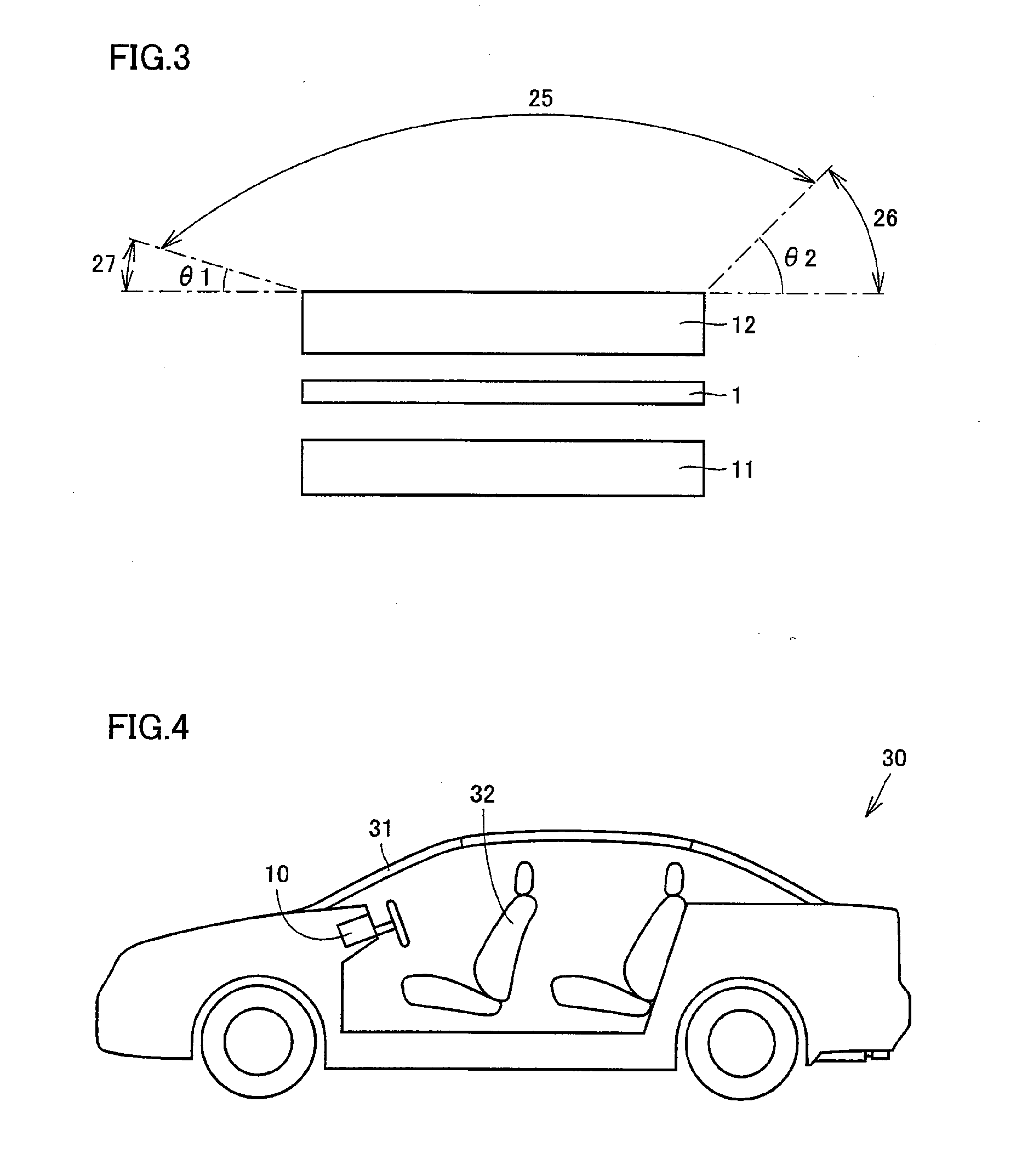
[0128]A light distribution control panel according to the present invention, a display device, and a vehicle serving as a mobile unit on which the display device is mounted will be described hereinafter with reference to FIGS. 1 to 5.

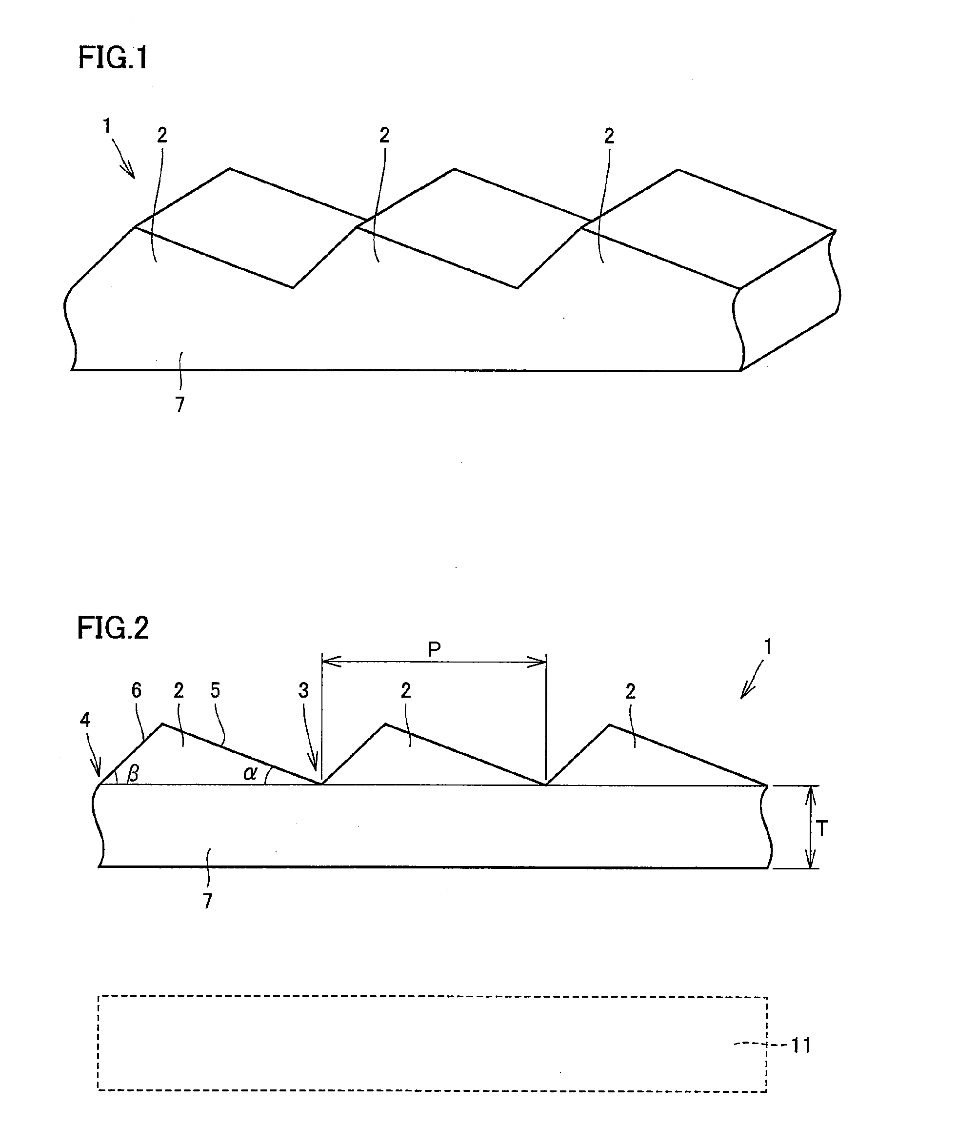
[0129]As shown in FIGS. 1 and 2, a light distribution control panel 1 according to the present invention includes a base body 7 made of a translucent resin and a plurality of convex portions 2 formed on a surface of base body 7. The plurality of convex portions 2 are formed to extend in parallel to one another. It is noted that the plurality of convex portions 2 may each be formed to extend linearly. A cross section in a direction perpendicular to a direction in which convex portion 2 extends has a triangular outline as shown in FIG. 2. It is assumed that angle β indicates an angle in one corner portion 4 of one convex portion 2. In addition, it is assumed that angle α indicates an angle in the other corner portion 3 located opposite to above one corner...

second embodiment

[0152]A second embodiment of the light distribution control panel according to the present invention will be described with reference to FIG. 6.

[0153]Light distribution control panel 1 shown in FIG. 6 has a structure basically similar to that of the light distribution control panel shown in FIGS. 1 and 2. Light distribution control panel 1 shown in FIG. 6 is, however, different from the light distribution control panel shown in FIGS. 1 and 2 in that a black film 8 is formed on the surface of one side surface 6 of convex portion 2 formed on one surface opposite to the light source (e.g., backlight 11 shown in FIG. 2) side of base body 7. With such a configuration as well, the effect similar to that of the light distribution control panel shown in FIGS. 1 and 2 can be obtained. In other words, above light distribution control panel 1 shown in FIG. 6 includes, as a light transmission suppressing portion, black film 8 serving as a light absorbing layer formed on one side surface 6 that ...

third embodiment

[0159]A third embodiment of the light distribution control panel according to the present invention will be described with reference to FIG. 8.

[0160]Light distribution control panel 1 shown in FIG. 8 has a structure basically similar to that of light distribution control panel 1 shown in FIGS. 1 and 2. Light distribution control panel 1 shown in FIG. 8 is, however, different from light distribution control panel 1 shown in FIGS. 1 and 2 in that black film 8 for blocking light that travels toward one side surface 6 as indicated by an arrow 13 is formed on a light source side surface 14 that is a back surface of base body 7, located opposite to the surface of base body 7 on the side where convex portion 2 is formed. Black film 8 is linearly formed to extend along one side surface 6. In addition, an end of black film 8 is at a distance L1 from a position on the back surface of base body 7 located directly below one corner portion 4 of convex portion 2. Furthermore, black film 8 has a w...


PUM

PropertyMeasurementUnit
angleaaaaaaaaaa
angleaaaaaaaaaa
angleaaaaaaaaaa

Abstract

There is provided a light distribution control panel that can suppress reflection on a glass surface in a mobile unit when the light distribution control panel is applied to a display device mounted on the mobile unit, and a display device for mounting on a mobile unit in which the light distribution control panel is used. A light distribution control panel includes a base body serving as a plate-like or sheet-like base material made of a translucent material, and the base body has a plurality of convex portions for light distribution control formed on one surface opposite to the backlight side of the base body. The plurality of convex portions are positioned to extend in parallel to one another. The light distribution control panel includes a light transmission / reflection suppressing portion (a surface of one side surface having higher roughness than that of a surface of the other side surface) for suppressing emission, from at least a part (one side surface) of a surface of the convex portion, of light incident from a surface of the base body on the light source side.

Description

TECHNICAL FIELD[0001]The present invention relates to a light distribution control panel, a display device for mounting on a mobile unit, a light distribution control sheet, an optical component, a lighting device, and a display device. More particularly, the present invention relates to a light distribution control panel that can control light distribution, and a display device for mounting on a mobile unit. Specifically, the present invention relates to a light distribution control sheet for efficiently emitting light from a light source in a particular direction, as well as a light distribution control panel and a display device in which the sheet is used. In addition, the present invention relates to an optical component that can be suitably used for viewing angle control. Furthermore, the present invention relates to a lighting device and a display device in which such an optical component is used.BACKGROUND ART[0002]A light distribution control panel that controls light distri...

Claims


Application Information

Patent Timeline
Patent Type & Authority Applications(United States)
IPC IPC(8): G02F1/13357F21V5/00G02B27/00
CPCB60K35/00B60K37/00B60K2350/206G02F2001/133607G02B5/045G02F1/133606B60K2350/2082B60K37/04B60K2370/152B60K2370/20B60K2370/25B60K2370/39G02F1/133607
Inventor YORITA, JUNTAKUSHIMA, MICHIKOSANO, TOMOMI
Owner SUMITOMO ELECTRIC IND LTD
Why Eureka
Try Eureka