

Autonomous mobile robot
- Summary
- Abstract
- Description
- Claims
- Application Information
AI Technical Summary
Benefits of technology
Problems solved by technology
Method used
Image

Examples
Embodiment Construction
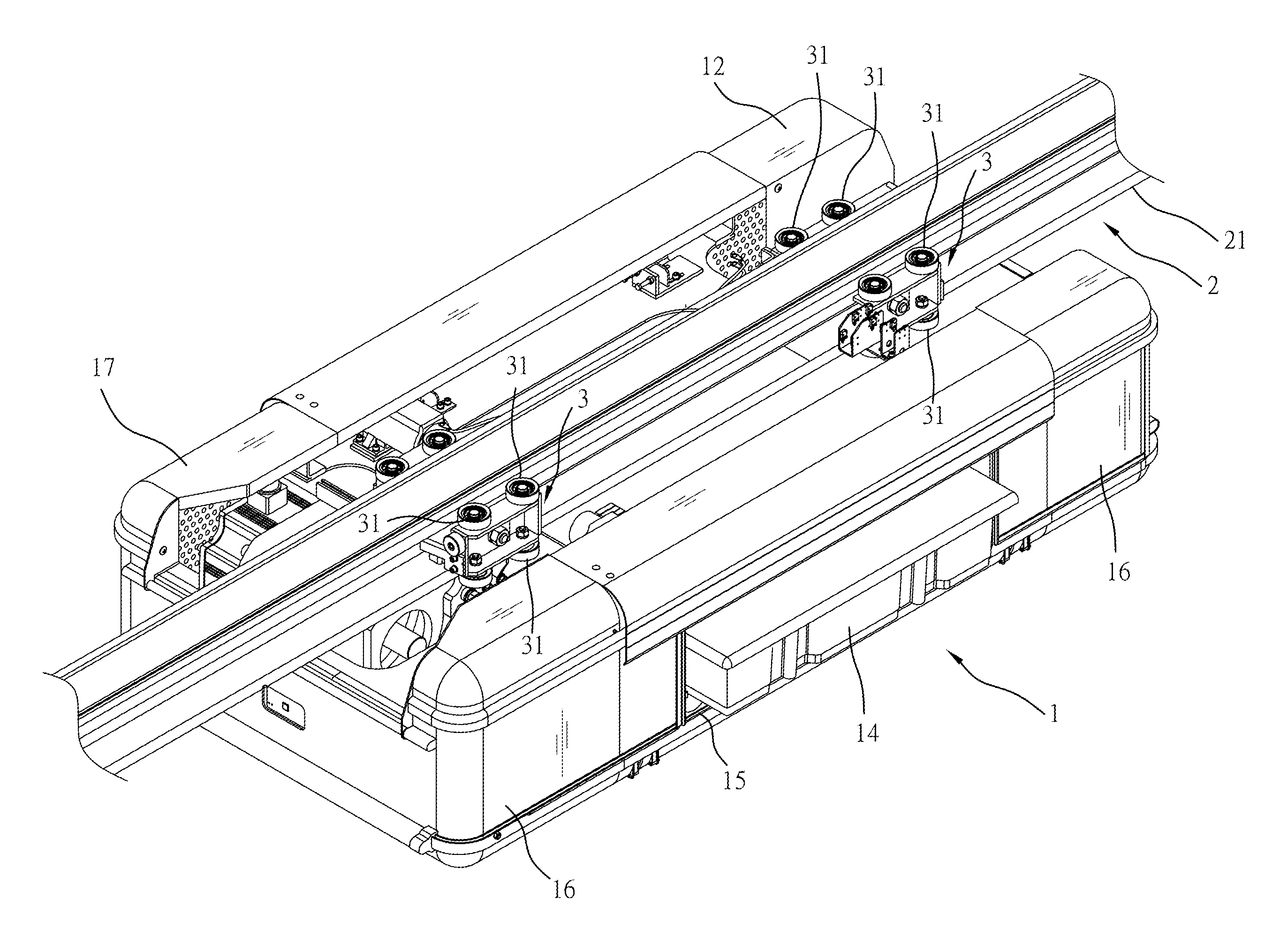
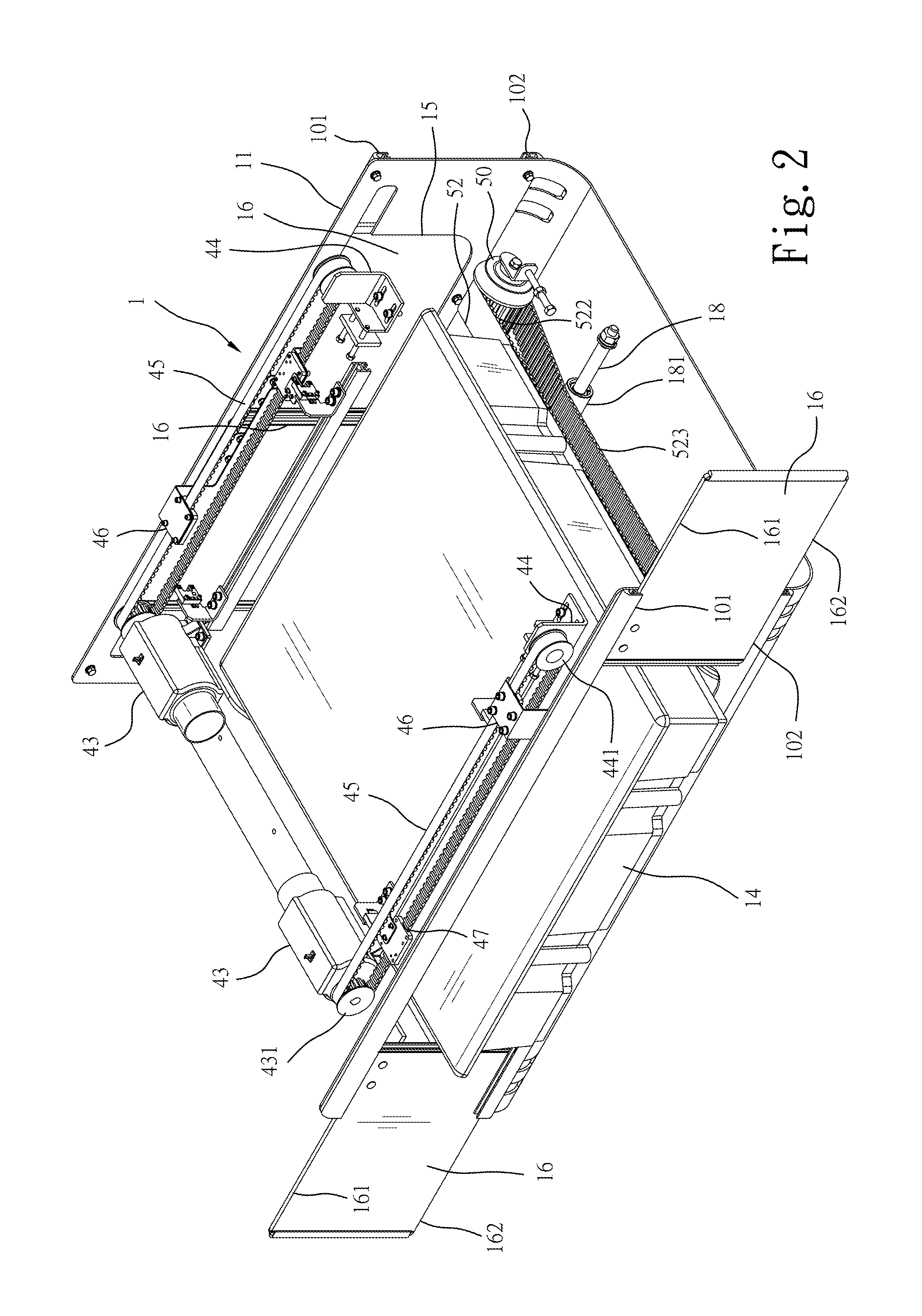
[0018]Referring to FIGS. 2-18, an autonomous mobile robot 1 is shown mounted on and movable along a track 2 (see FIG. 7) to transport materials. The autonomous mobile robot 1 can be controlled to move along the track 2 and to stop at every selected location. The track 2 supports and guides movement of the autonomous mobile robot 1.
[0019]The autonomous mobile robot 1 comprises a housing 11, a front cover 12 and a rear cover 17 covered on the front and rear sides of the housing 11 (see FIG. 7), front and rear friction transmission mechanisms 3 respectively mounted on the housing 11 at the front and rear sides, each friction transmission mechanism 3 having the friction wheels 30;31 thereof (see FIG. 6) respectively pivotally disposed at the left and right sides and kept in contact with the bottom rail 21 of the track 2 (see FIG. 6), a robot driving motor 41 mounted in one of the front and rear sides inside the housing 11, a driving wheel 32 kept in contact with the bottom surface 212 o...
PUM
 Abstract
Description
Claims
Application Information