Lighting device

a technology of led lamps and light tubes, which is applied in the direction of lighting support devices, lighting and heating devices, instruments, etc., can solve the problems of deteriorating the luminous efficiency of led lamps, generating a large amount of heat, and generating a large amount of heat, and achieve excellent energy efficiency

Inactive Publication Date: 2011-07-21
IRIS OHYAMA
View PDF7 Cites 73 Cited by
  • Summary
  • Abstract
  • Description
  • Claims
  • Application Information

AI Technical Summary

Benefits of technology

[0011]An object of the present invention is to provide a lighting device excellent in energy efficiency.
[0012]A detailed object of the present invention is to provide a lighting device which is excellent in energy efficiency and can realize space-saving.
[0013]Another detailed object of the present invention is to provide a lighting device in the form of an LED lamp which emits light with uniform luminance and can increase the luminous efficiency.

Problems solved by technology

However, a halogen lamp emits light by supplying electricity to a filament as a resistor and generates a large amount of heat along with luminescence.
Therefore, as compared with a fluorescent lamp, for example, the energy efficiency is inferior.
This deteriorates the luminous efficiency of the LED lamp X1.
This also deteriorates the luminous efficiency of the LED lamp X1.

Method used


Image

  • Lighting device
  • Lighting device
  • Lighting device

Examples


Embodiment Construction

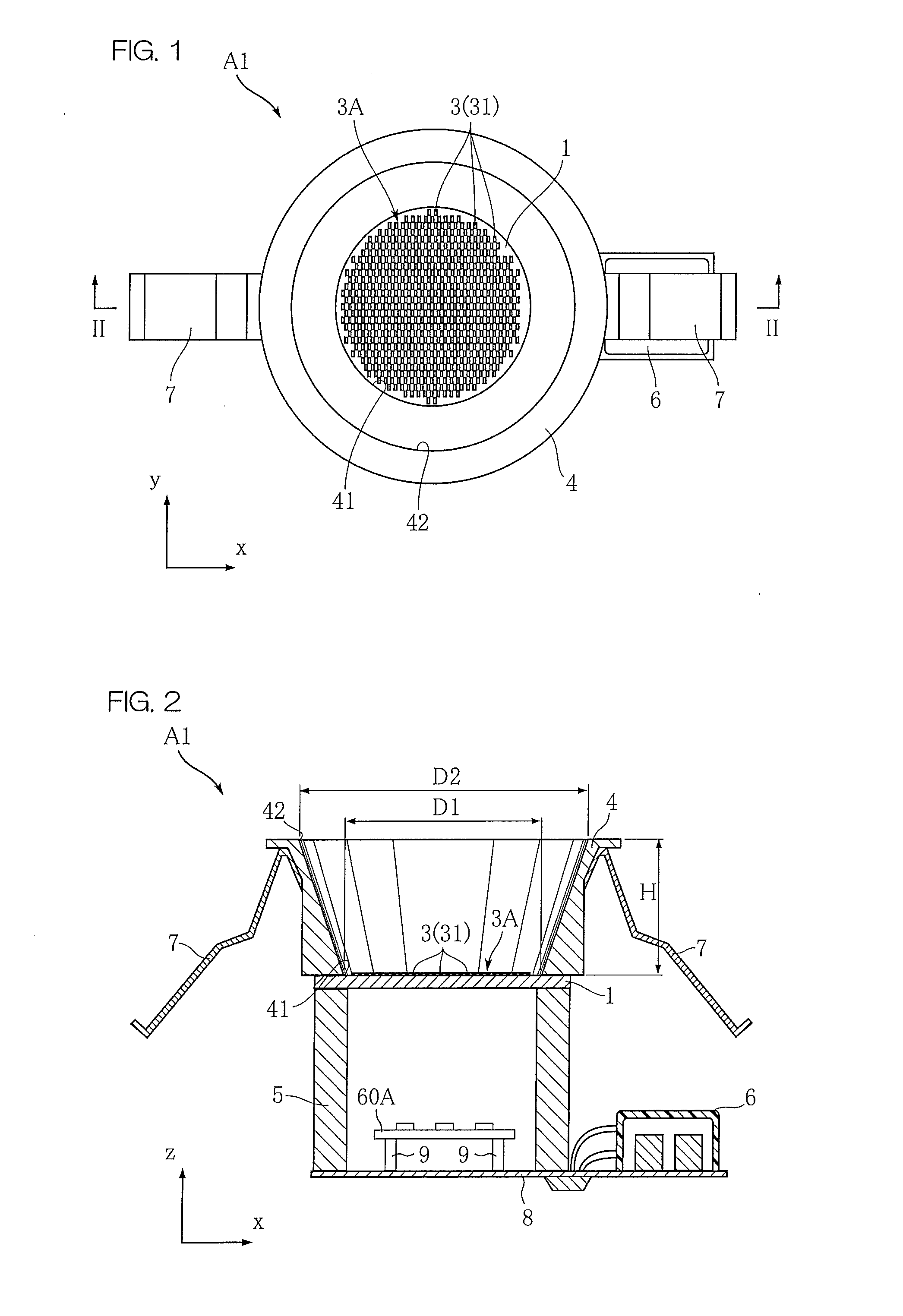
[0154]FIG. 1 and FIG. 2 show a lighting device according to a first preferred embodiment of the present invention. The lighting device A1 of the present preferred embodiment includes a substrate 1, a plurality of LED modules 3, a reflector 4, a housing 5, a connector 6, and a holder 7. The lighting device A1 may be used as a so-called downlight by being installed in an opening space provided on a ceiling with an upside down position in the z direction of FIG. 2.

[0155]The substrate 1 is, for example, an aluminum plate the surface of which is insulated, and is for mounting a plurality of LED modules 3. In the present preferred embodiment, the substrate 1 is circular, and has a diameter of approximately 66 mm. The region in which the plurality of LED modules 3 are mounted is a circular region with a diameter of approximately 50 to 60 mm.

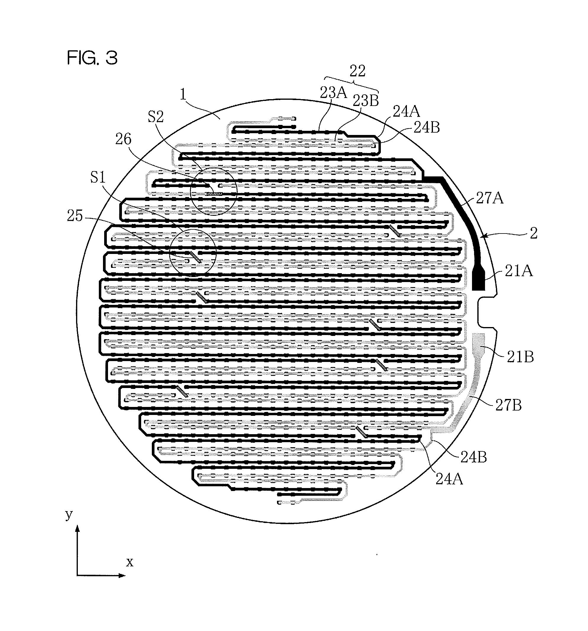
[0156]As shown in FIG. 3, on the substrate 1, a wiring pattern 2 is formed. The wiring pattern 2 is made of a metal film of, for example, copper, and i...


PUM


Abstract

A lighting device includes a substrate and a planar light source portion including a plurality of LED chips arrayed on the substrate. The planar light source portion faces an illumination space (space to be illuminated) by a predetermined opening area. The plurality of LED chips are arrayed on the substrate such that the mounting density with respect to the opening area is not less than 3 / cm2, and accordingly, a planar light source is formed.

Description

TECHNICAL FIELD [0001]The present invention relates to a lighting device using light-emitting diodes (hereinafter, referred to as LEDs) as a light source. This lighting device may be mounted on, for example, a ceiling of a building, and used as a so-called downlight which performs downward illumination to a floor surface, etc. Also, this lighting device may have a form of an LED lamp which can be used as an alternative to the fluorescent lamp.BACKGROUND ART [0002]A downlight is a lighting device which is mounted in advance on a ceiling, etc., of a building, and is used to create, for example, a warm atmosphere by illuminating a floor or a table, etc. (for example, refer to Patent document 1). A conventional lighting device to be used for a downlight includes, for example, a halogen lamp as a light source. A halogen lamp is a so-called point light source which emits light in various directions. In order to direct light from the halogen lamp toward a desired range, the lighting device...

Claims


Application Information

Patent Timeline
Patent Type & Authority Applications(United States)
IPC IPC(8): H05B37/02F21V21/00F21V7/00F21V15/01H05B44/00
CPCF21S8/02F21Y2101/02H05B33/0803F21Y2105/001H01L2924/181H01L2224/48091H01L2224/48227F21Y2105/10F21Y2115/10F21V23/005F21S4/28F21V3/06H05B45/40H05B45/345H01L2924/00014H01L2924/00012F21V23/02F21K9/272F21K9/278F21S8/04F21V15/01
Inventor FUJITA, TOSHIYUKIWATANABE, TOSHIOKAWABATA, YUSAKU
Owner IRIS OHYAMA
Why Eureka
Try Eureka