Constant Temperature LED Driver Circuit

a driver circuit and constant temperature technology, applied in the direction of instruments, light sources, electroluminescent light sources, etc., can solve the problems of significantly longer useful life and significantly shorter and achieve the effect of sacrificing luminosity, increasing lumen depreciation, and maximizing the useful life of leds

Active Publication Date: 2011-08-18
COTTRELL BRIAN
View PDF2 Cites 31 Cited by
  • Summary
  • Abstract
  • Description
  • Claims
  • Application Information

AI Technical Summary

Benefits of technology

[0013]Another object of this invention is to maximize the useful lifetime of an LED by sacrificing luminosity in conditions that would otherwise cause an increase in lumen depreciation.
[0014]Yet another object of this invention is to provide an LED light source that maximizes luminous output so long as it can do so without sacrificing longevity.
[0015]Still another object of this invention is to provide an LED light source with a useful lifetime that can be predicted with reasonable accuracy.

Problems solved by technology

This means the useful life may be significantly shorter if the LED is allowed to operate in an environment that regularly exceeds 30 degrees.
Also, if kept in much lower temperatures, the LED may have a significantly longer lifetime.
However, along with driving current, ambient temperature also plays an important role in LEDs overheating.

Method used


Image

  • Constant Temperature LED Driver Circuit
  • Constant Temperature LED Driver Circuit
  • Constant Temperature LED Driver Circuit

Examples


Embodiment Construction

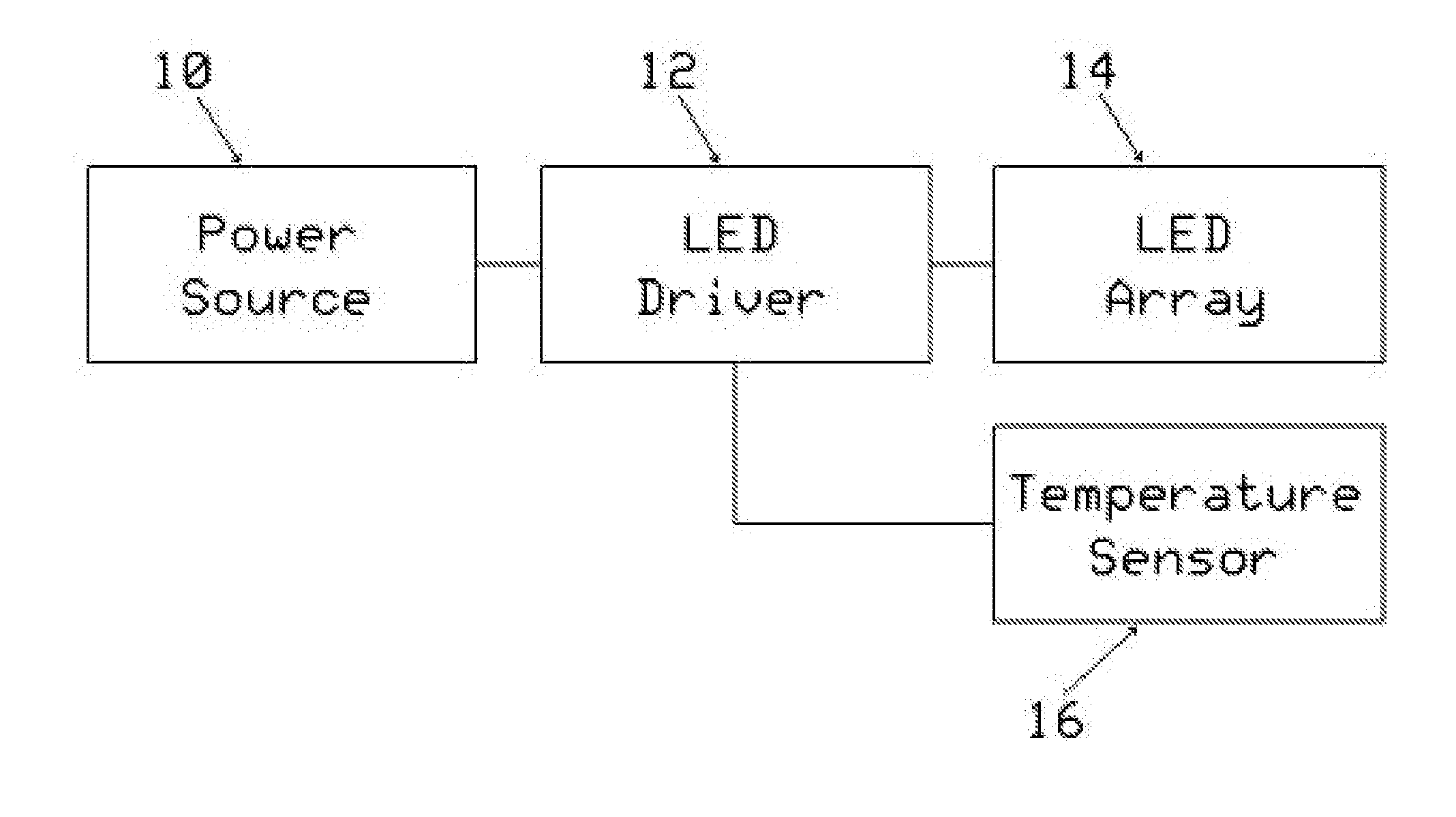
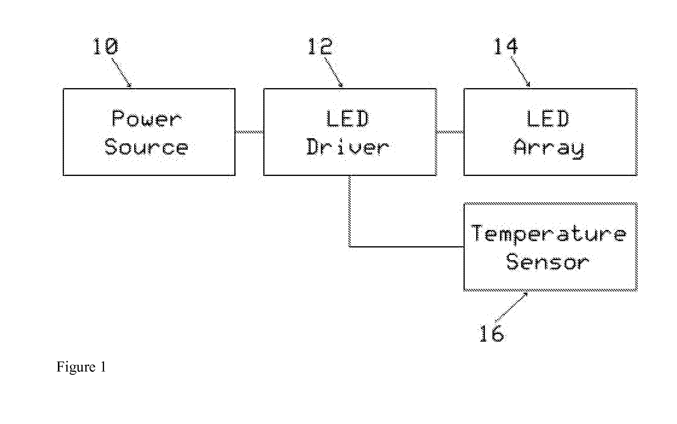
[0021]Referring now to the invention in more detail, in FIG. 1 there is shown a simple block diagram for the general layout of the preferred embodiment of a constant temperature LED driver circuit. An AC (alternating current) or DC (direct current) power source 10 powers an LED driver 12, which in turn drives an LED array 14. The LED driver 12 accepts an input signal from a temperature sensing means 16, which measures the temperature of the LED array 14. The LED driver 12 uses this signal to adjust the average current provided to the LED array 14.

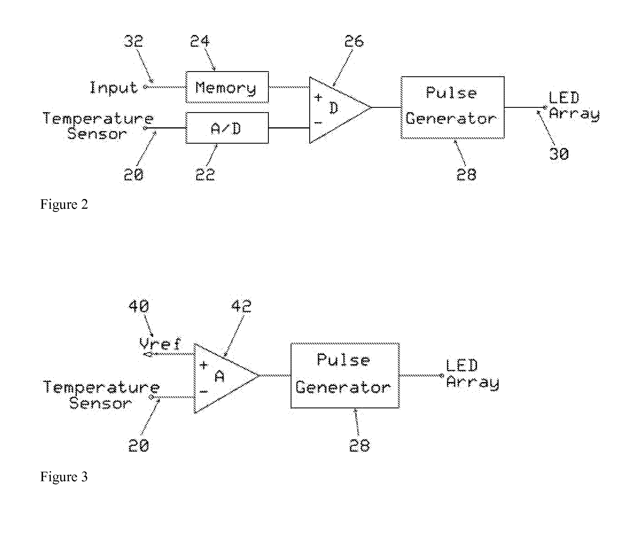
[0022]Referring now to FIG. 2, there is shown a detailed diagram of the LED driver 12 of FIG. 1. The LED driver 12 preferably includes an analog input 20, an analog to digital converter 22, memory storage 24, a digital comparator 26, and pulse generator 28 with a variable pulse width. The output 30 of the pulse generator 28 drives the LED array 14.

[0023]As shown in FIG. 2, the analog input 20 is coupled to the output of the temperature sens...


PUM


Abstract

A constant temperature LED driver circuit for controlling the rate of lumen depreciation and therefore useful lifetime of an LED array by keeping the LEDs at a fixed temperature. A temperature sensing means, which measures the temperature of the LEDs, is coupled to a variable power source that drives the LED array. The current provided to the LED array is adjusted in response to the temperature sensing means to ensure that the LEDs remain at a constant temperature regardless of changes in ambient temperature.

Description

CROSS-REFERENCE TO RELATED APPLICATIONS[0001]Not ApplicableSTATEMENT REGARDING FEDERALLY SPONSORED RESEARCH OR DEVELOPMENT[0002]Not ApplicableREFERENCE TO SEQUENCE LISTING, A TABLE, OR A COMPUTER PROGRAM LISTING COMPACT DISK APPENDIX[0003]Not ApplicableBACKGROUND OF THE INVENTION[0004]The present invention is directed to an LED (light emitting diode) light source with a driving circuit to drive the LED light source. More particularly the present invention is directed to an LED light source with driving circuitry designed to maintain a constant temperature and therefore a constant useful life for the LED. The luminosity of the LED is adjusted to compensate for fluctuations in ambient temperature in order to prevent excessive depreciation in luminosity over time caused by overheating.[0005]The amount of light produced by an electric light source decreases with time in a process known as lumen depreciation. For an LED, lumen depreciation is primarily caused by heat generated at the LED...

Claims


Application Information

Patent Timeline
Patent Type & Authority Applications(United States)
IPC IPC(8): H05B37/02
CPCH05B33/089H05B45/18H05B45/56H05B45/58
Inventor COTTRELL, BRIAN
Owner COTTRELL BRIAN
Why Eureka
Try Eureka