Bone Plate

a technology of bone plate and thread, applied in the field of bone plate, can solve the problem of damage to the thread of the through hol

Active Publication Date: 2011-12-08
DEPUY SYNTHES PROD INC
View PDF2 Cites 31 Cited by
  • Summary
  • Abstract
  • Description
  • Claims
  • Application Information

AI Technical Summary

Benefits of technology

[0004]The present invention relates to a bone plate being able to receive at least a central bone screw in such a way that the thread in the through hole in the bone plate is not damaged when a bone screw is inserted.

Problems solved by technology

However, one problem that can arise is that if the bone screw is not exactly coaxially inserted with respect to the through hole axis the thread of the through hole can be damaged.

Method used


Image

  • Bone Plate
  • Bone Plate
  • Bone Plate

Examples


Embodiment Construction

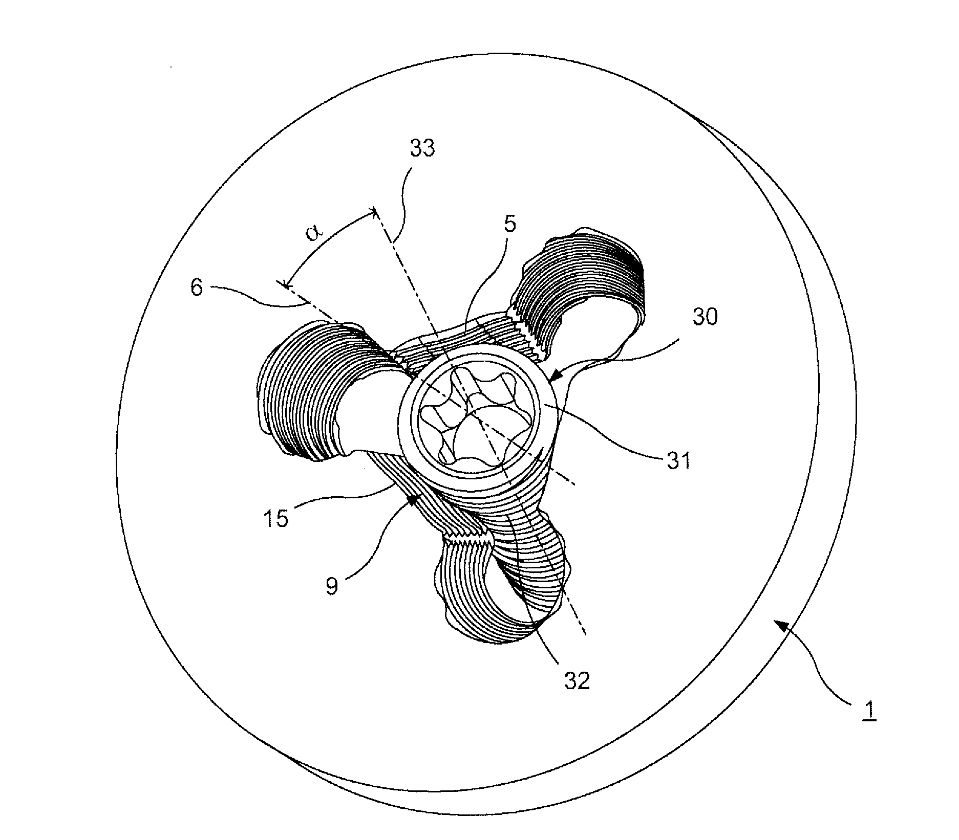
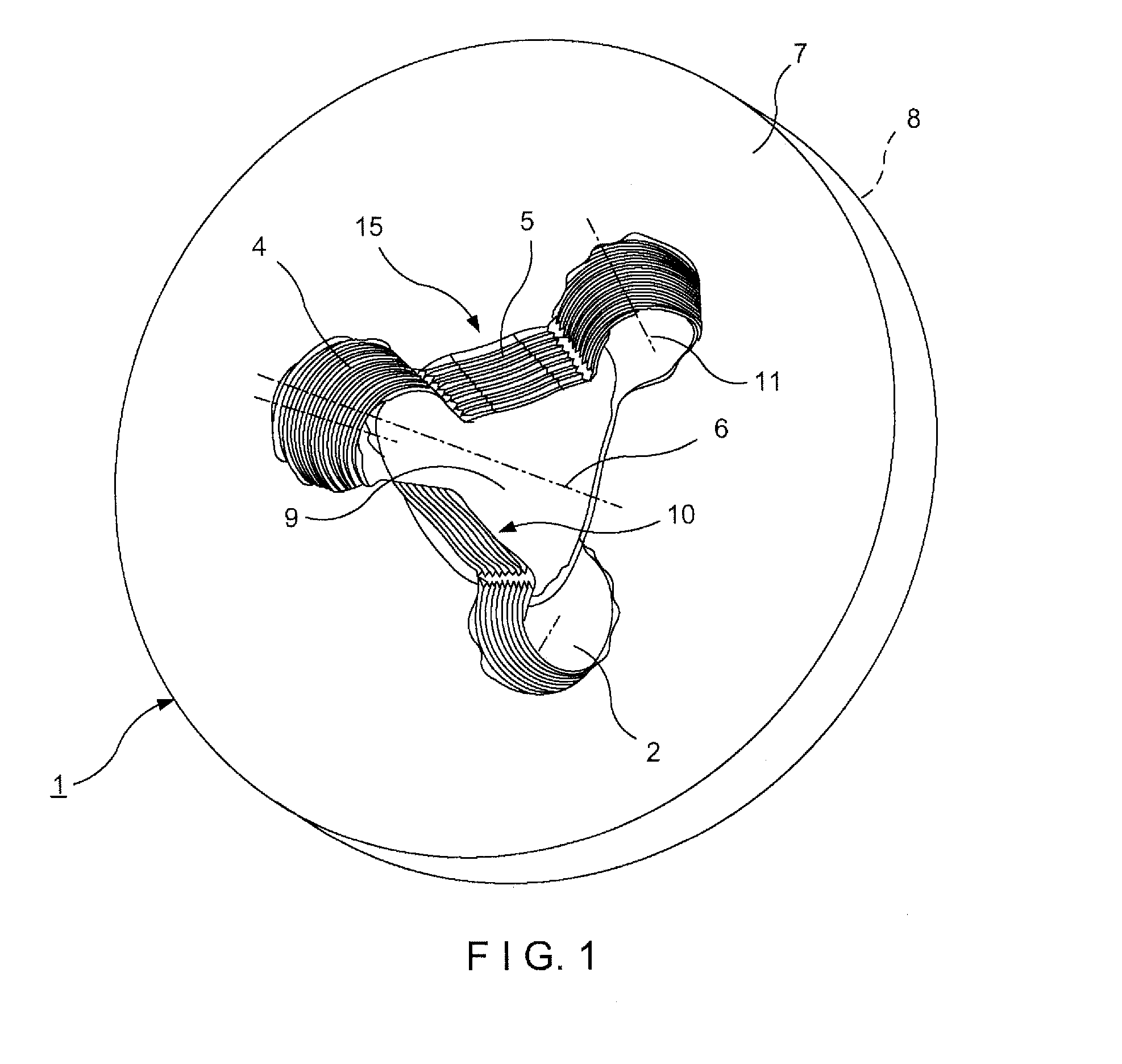
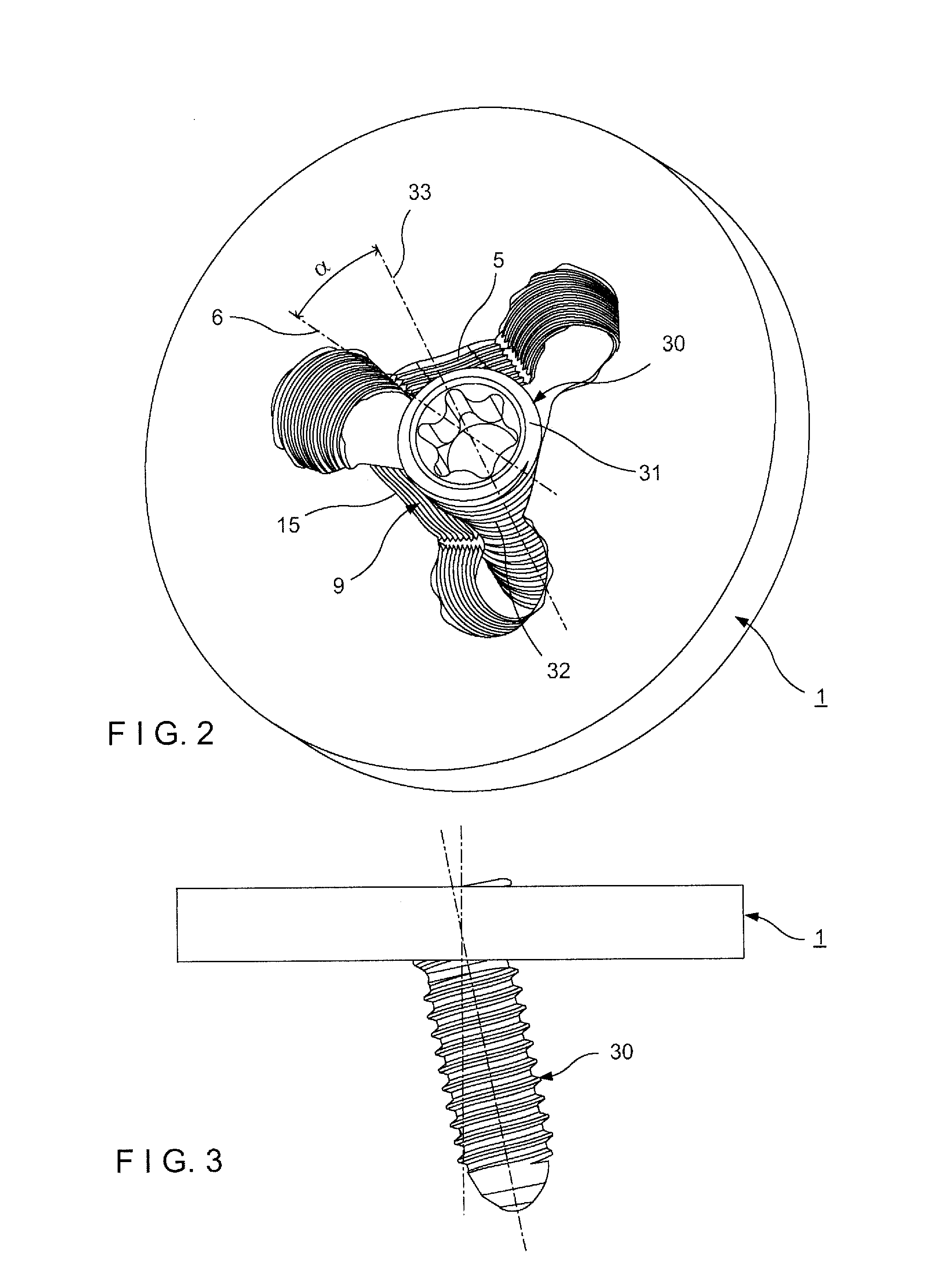
[0061]The present invention is directed to a system for the fixation of fractured or otherwise damaged bones via one or both of a variable angle insertion and a fixed angle insertion of a bone screw through a bone plate hole. Specifically, a bone plate according to the present invention is provided with a central through hole configured to receive a first bone screw therethrough at any user selected angle relative to a longitudinal axis of the through hole within a permitted range of angulation. A plurality of second bone screws may also be inserted through outlying portions of the bone plate hole, each defining a separate plate hole axis. The outlying portions of the bone plate hole are formed as substantially circular peripheral holes configured to overlap and be open to the through hole to form a composite hole having any of a plurality of shapes depending on the placement and number of the peripheral holes relative to the through hole, as will be discussed in greater detail with...


PUM


Abstract

A bone plate includes a first through hole extending through the plate along a first longitudinal axis from a proximal surface of the plate to a bone-facing distal surface thereof which, when the plate is placed on a target portion of bone in a desired orientation, faces the bone. An outer wall of the first through hole includes three wall sections provided with projections for receiving a screw head of a bone screw. The three wall sections are straight or convex.

Description

PRIORITY CLAIM[0001]The present application claims priority to U.S. Provisional Application Ser. No. 61 / 350,691 filed on Jun. 2, 2010 and entitled “Bone Plate,” the entire disclosure of which is incorporated herein by reference.FIELD OF THE INVENTION[0002]The present invention generally relates to a bone plate which can be fixed to a bone by means of bone screws. More particularly, the present invention relates to a bone plate having a through hole with an internal thread to threadably receive a locking bone screw.BACKGROUND OF THE INVENTION[0003]Bone plates with through holes comprising a cylindrical or conical interior thread to receive a locking head bone screw are commonly used in the field of osteosynthesis. Due to the threaded connection between the head of the bone screw and the through hole in the bone plate the bone screw is firmly anchored in the through hole in the bone plate. However, one problem that can arise is that if the bone screw is not exactly coaxially inserted ...

Claims


Application Information

Patent Timeline
Patent Type & Authority Applications(United States)
IPC IPC(8): A61B17/80
CPCA61B17/7059A61B17/8061A61B17/8057A61B17/8052A61B17/80A61L27/04A61B17/86
Inventor ROTH, BEATHULLIGER, URS
Owner DEPUY SYNTHES PROD INC
Why Eureka
Try Eureka