Blower fan and method of manufacturing the same

a technology of blower fan and fan body, which is applied in the direction of positive displacement liquid engine, piston pump, liquid fuel engine, etc., can solve the problems of increasing vibration, increasing strength, and increasing heat generated by increasingly dense electronic devices, so as to reduce size and weight, maintain reliability for a long time, and reduce the effect of size and weigh

Inactive Publication Date: 2011-12-29
NIPPON DENSAN CORP
View PDF8 Cites 12 Cited by
  • Summary
  • Abstract
  • Description
  • Claims
  • Application Information

AI Technical Summary

Benefits of technology

[0013]Because both the portion arranged to support the bearing and the portion arranged to support the stator are defined by the metallic members, a sufficient vibration-resistant strength of the bearing support portion is secured even when the blower fan is caused to rotate at a great speed, and heat that is generated from the stator is sufficiently radiated away even when the blower fan is caused to operate for a long time. Thus, it is possible to realize a blower fan that is able to maintain reliability for a long time even when the blower fan is caused to rotate at a great speed, and which is also able to satisfy the demand for reduced size and weight.
[0014]According to various preferred embodiments of the present invention, it is possible to realize a blower fan that is able to maintain reliability for a long time even when the blower fan is caused to rotate at a great speed, and which is able to cope with a demand for reduced size and weight.

Problems solved by technology

Meanwhile, as electronic devices have become increasingly dense in recent years the amount of heat generated by these increasingly dense electronic devices has also increased.
The outer-rotor motors, however, may cause a problem in terms of strength, because an increased rotational speed of the blower fan leads to an increased vibration resulting from the great moment of inertia of the outer-rotor motors.
The technique described in U.S. 2009 / 0180901, however, has problems because its motor support portion is made of a solid one-piece member defined by only a plastic or a metal.
That is, in the case where the motor support portion is made of a plastic or a metal, the support portion arranged to support the bearing is also made of the plastic or the metal, and it is therefore difficult to secure a sufficient vibration-resistant strength for an increased rotational speed of the blower fan.
Also, in the case where the support portion arranged to support the stator is made of a plastic or a metal, vibration that is generated in the stator may be transmitted to a housing through the plastic or the metal when the blower fan is caused to rotate at a great speed.
Moreover, if the blower fan is caused to rotate at a great speed for a long time, the stator may generate too much heat to allow a sufficient heat radiation effect.
It is therefore difficult to maintain reliability of the blower fan for a long time when the blower fan is caused to rotate at a great speed.

Method used


Image

  • Blower fan and method of manufacturing the same
  • Blower fan and method of manufacturing the same
  • Blower fan and method of manufacturing the same

Examples


Embodiment Construction

[0025]Hereinafter, preferred embodiments of the present invention will be described in detail with reference to the accompanying drawings. In the description of the preferred embodiments, a direction parallel or substantially parallel to a rotation axis and a radial direction centered on the rotation axis will be referred to simply as an “axial direction” and a “radial direction”, respectively. Note that the present invention is not limited to the preferred embodiments described below. Also note that the preferred embodiments described below may be combined with other preferred embodiments of the present invention.

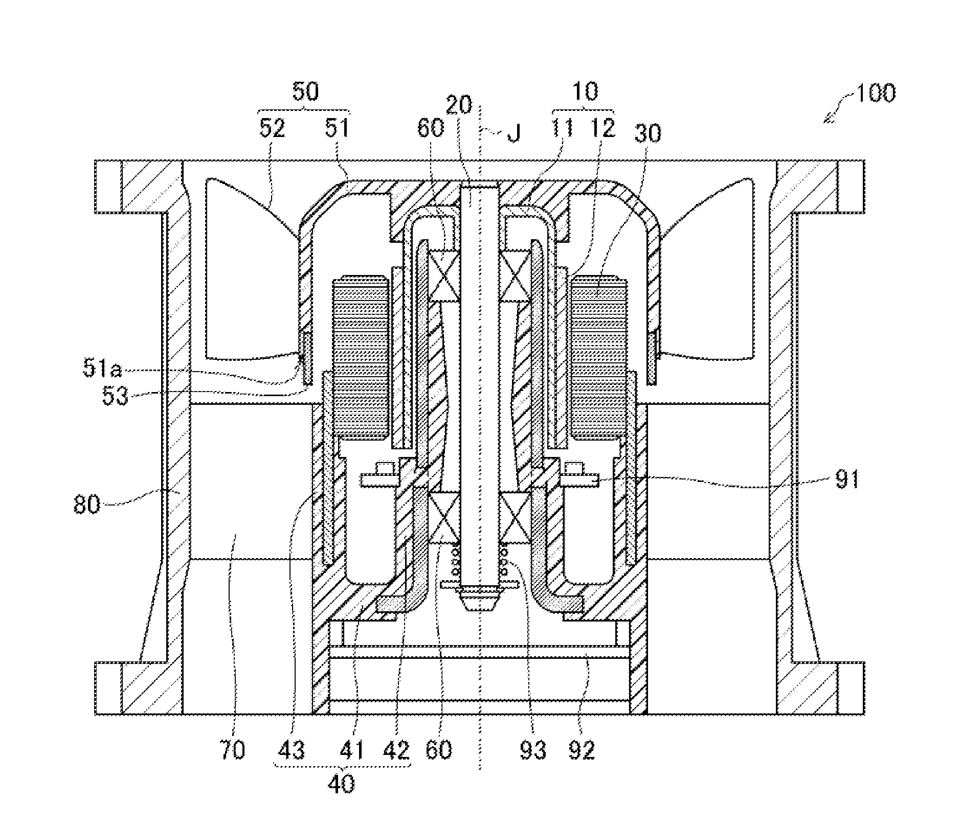
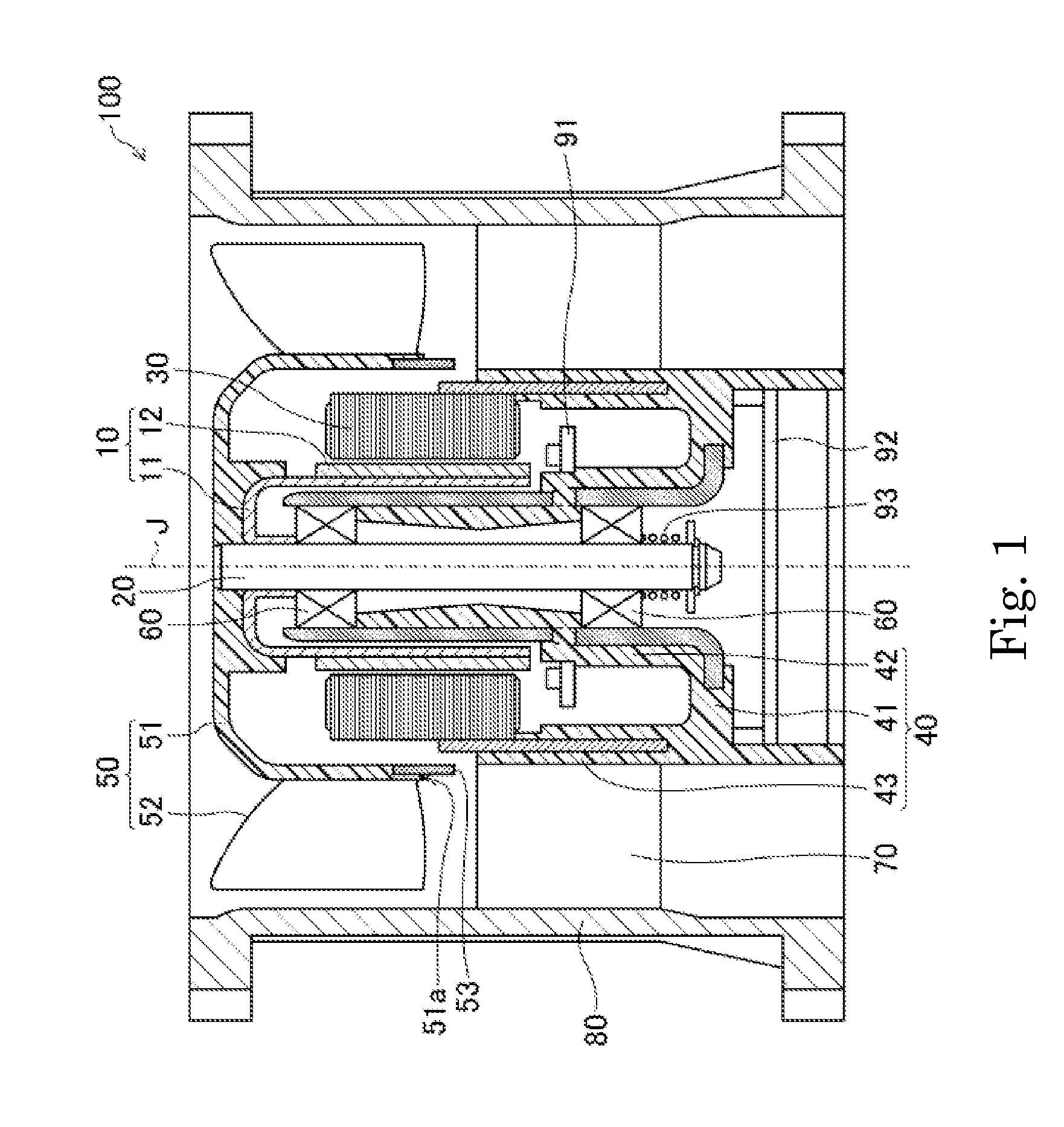
[0026]FIG. 1 is a schematic cross-sectional view illustrating the structure of a blower fan 100 according to a preferred embodiment of the present invention. The blower fan 100 according to a preferred embodiment of the present invention is a so-called axial fan.

[0027]Referring to FIG. 1, the blower fan 100 includes a rotor 10 arranged to rotate about a rotation axis J tog...


PUM

PropertyMeasurementUnit
rotational speedaaaaaaaaaa
speedaaaaaaaaaa
strengthaaaaaaaaaa

Abstract

A blower fan includes a rotor arranged to rotate about a rotation axis together with a shaft, a stator arranged radially outward of the rotor and opposite the rotor, a motor support portion arranged to support the shaft through a bearing such that the shaft is rotatable, and an impeller arranged to rotate together with the shaft. The motor support portion includes a base portion, a bearing support portion arranged to support the bearing, and a stator support portion arranged to support the stator. Each of at least a portion of the bearing support portion which is in contact with the bearing and at least a portion of the stator support portion which is in contact with the stator is defined by a metallic member coupled to the base portion, which is made of a resin, preferably through, for example, insert molding.

Description

BACKGROUND OF THE INVENTION[0001]1. Field of the Invention[0002]The present invention relates to a blower fan used, for example, to cool an electronic device, and a method of manufacturing such a blower fan.[0003]2. Description of the Related Art[0004]Outer-rotor motors, in which a rotor is arranged radially outward of a stator, have been predominantly used as motors for driving blower fans because they typically provide an easier assembling procedure, a reduced number of parts, and so on. In addition, in terms of performance, the outer-rotor motors typically have a greater moment of inertia and are able to achieve increased driving torque, and therefore are more easily able to maintain a constant rotational speed.[0005]Meanwhile, as electronic devices have become increasingly dense in recent years the amount of heat generated by these increasingly dense electronic devices has also increased. As a result, there has been a demand for blower fans used to cool such electronic devices t...

Claims


Application Information

Patent Timeline
Patent Type & Authority Applications(United States)
IPC IPC(8): F01B23/08B23P15/00
CPCF04D29/646H02K15/14H02K1/185H02K5/1735Y10T29/49236F04D25/0606H02K5/08
Inventor TAKESHITA, HIDENOBU
Owner NIPPON DENSAN CORP
Why Eureka
Try Eureka