Rotating transformer for supplying the field winding in a dynamoelectric machine

a technology of dynamoelectric machines and rotating transformers, which is applied in the direction of motor/generator/converter stoppers, dynamo-electric converter control, instruments, etc., can solve the problems of limiting design freedom, requiring a relatively large amount of space for auxiliary generators such as this, and being susceptible to wear

Inactive Publication Date: 2012-02-16
ALSTOM TECH LTD
View PDF7 Cites 6 Cited by
  • Summary
  • Abstract
  • Description
  • Claims
  • Application Information

AI Technical Summary

Problems solved by technology

However, these are susceptible to wear.
However, an auxiliary generator such as this requires a relatively large amount of space.
This design allows the rotating transformer to be arranged only at the end of the rotor shaft, in practice, and this considerably restricts the design freedom, as a result of which this solution is particularly unsuitable when large generators have to be used.
However, this arrangement also greatly restricts the possible forms of the dynamoelectrical machine.

Method used


Image

  • Rotating transformer for supplying the field winding in a dynamoelectric machine
  • Rotating transformer for supplying the field winding in a dynamoelectric machine
  • Rotating transformer for supplying the field winding in a dynamoelectric machine

Examples


Embodiment Construction

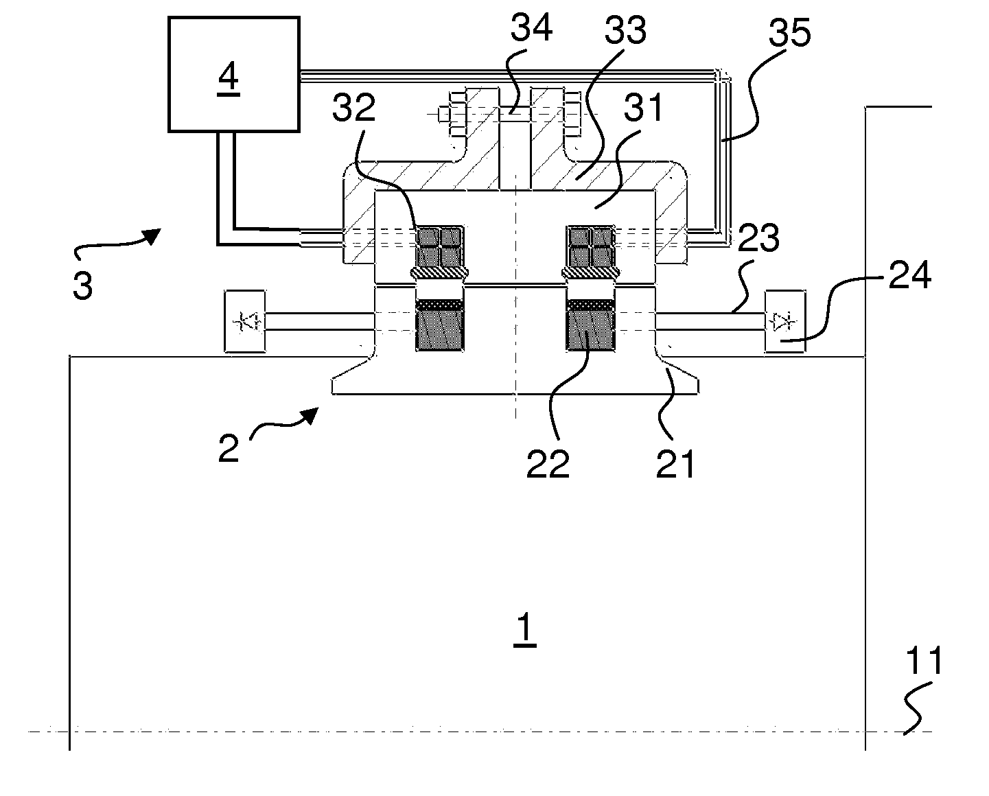
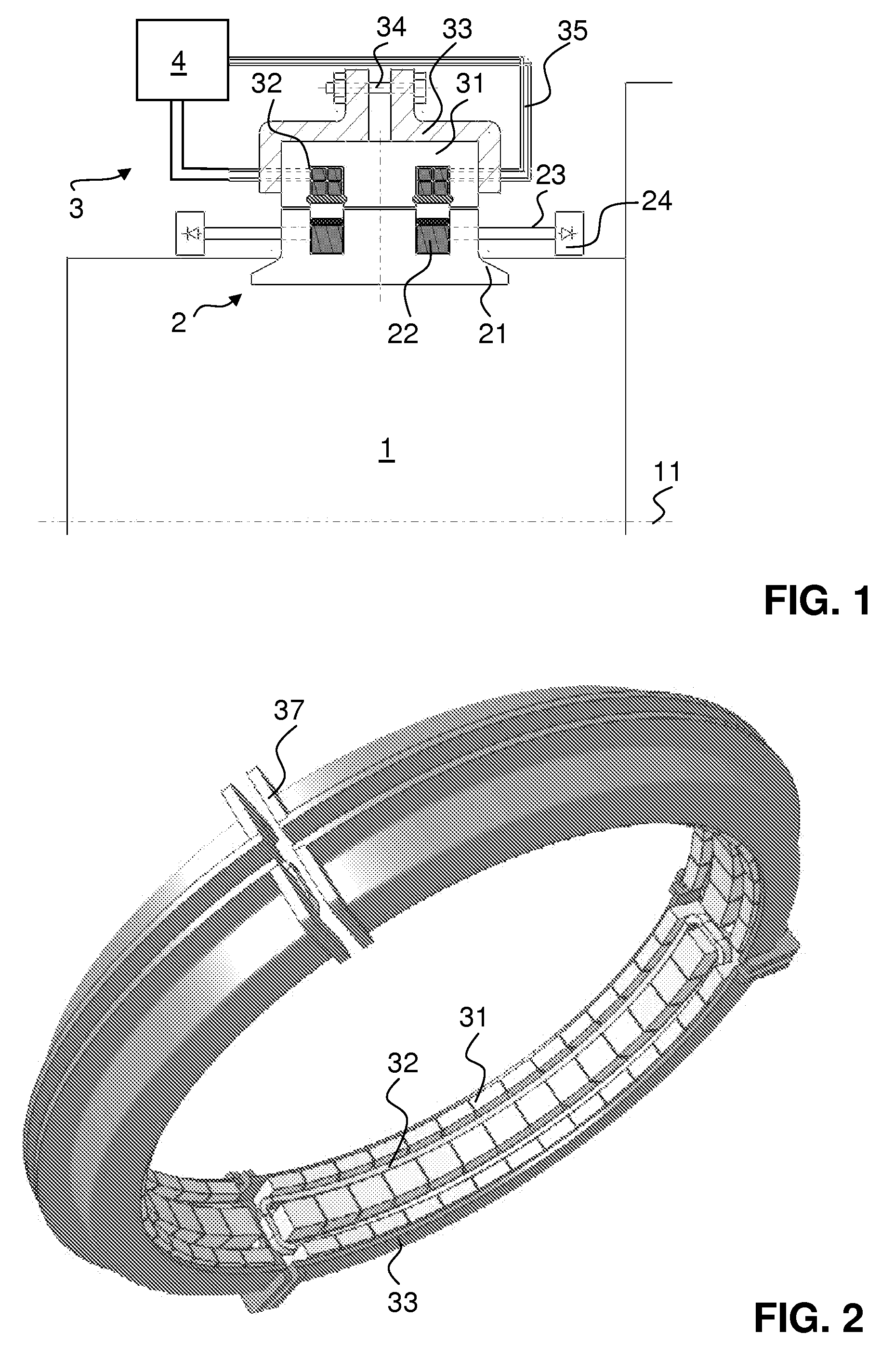
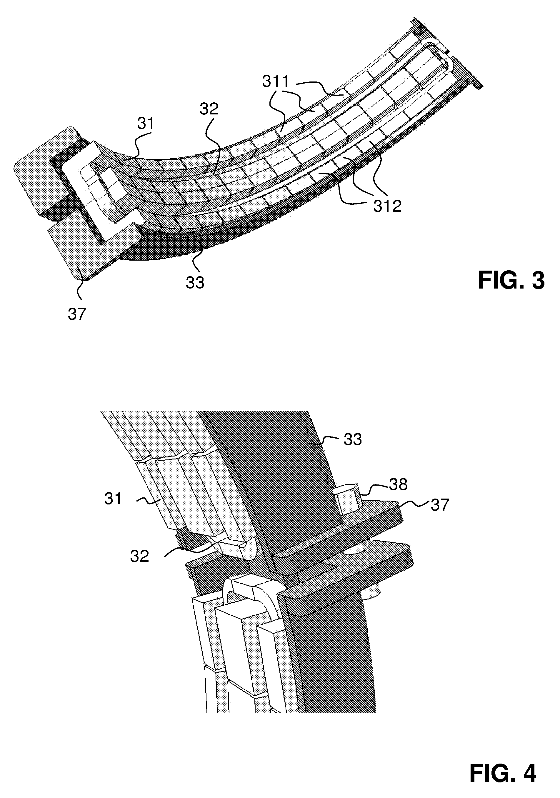
[0019]In an embodiment of the present invention, an apparatus is provided for transmission of electrical power from a stator to a rotor which can rotate, which apparatus can be designed in a space-saving manner, is simple to assemble, and allows greater power levels to be transmitted with less dependency on the rotation angle.

[0020]In an embodiment, an apparatus is provided for transmission of electrical power from a stator to a rotor, which apparatus has:[0021]an AC voltage source for production of an AC voltage;[0022]a stator having a primary winding arrangement which is electrically fed from the AC voltage source; and[0023]a rotor having a secondary winding arrangement with one or more secondary windings, which is inductively coupled to the primary winding arrangement, with the rotor being arranged such that it can rotate about a rotating axis and defining a rotation direction.

[0024]In an embodiment, this apparatus is distinguished in that the primary winding arrangement has at l...


PUM

PropertyMeasurementUnit
operating frequencyaaaaaaaaaa
frequencyaaaaaaaaaa
frequencyaaaaaaaaaa

Abstract

An apparatus for transmission of electrical power includes an AC voltage source configured to produce AC voltage. A stator includes a primary winding arrangement electrically fed from the AC voltage source, the primary winding arrangement having at least two primary windings. A rotor includes a secondary winding arrangement inductively coupled to the primary winding arrangement of the stator, the rotor being rotatable in a rotation direction about a rotation axis. The rotation axis does not pass through the at least two primary windings, and the at least two primary windings each extend over a predetermined sector with respect to the rotation direction and are disposed offset with respect to one another with in the rotation direction.

Description

CROSS REFERENCE TO PRIOR APPLICATIONS[0001]This application is a continuation of International Patent Application No. PCT / EP2010 / 052940, filed on Mar. 9, 2010, which claims priority to Swiss Application No. CH 00364 / 09, filed on Mar. 11, 2009. The entire disclosure of both applications is incorporated by reference herein.FIELD[0002]The present invention relates to an apparatus for transmission of electrical power from a stator to a rotor. An apparatus such as this is also referred to as a rotating transformer. The invention also relates to a dynamoelectrical machine which is equipped with a rotating transformer.BACKGROUND[0003]Electrical generators which are in the form of synchronous machines have one or more field windings on the rotor. A field winding is a conductor arrangement which produces a constant magnetic field during operation, which constant field rotates with the rotor, in order to induce an AC voltage in the windings of the stator. Brushes and sliprings may be provided...

Claims


Application Information

Patent Timeline
Patent Type & Authority Applications(United States)
IPC IPC(8): H02P25/02H01F38/18
CPCH01F38/18H02K11/0094H02K11/042H02K19/26H02K19/36
Inventor ZADEH, HOSSEIN SAFARI
Owner ALSTOM TECH LTD
Why Eureka
Try Eureka