Expandable Bone Implant

a bone implant and expandable technology, applied in the field of implants, can solve the problems of difficult to achieve optimal esthetics, and the prosthetic held at an ideal rotational orientation by the implant may not have the ideal vertical position,

Active Publication Date: 2012-05-24
ZIMMER DENTAL INC
View PDF4 Cites 10 Cited by
  • Summary
  • Abstract
  • Description
  • Claims
  • Application Information

AI Technical Summary

Problems solved by technology

The surgical procedure for inserting the threaded implants, however, can be complicated and requires that the threaded implants be turned into place, which further requires the use of special tools and inserts.
Also with threaded implants, it is often difficult to achieve optimal esthetics because the geometry of the thread establishes a fixed relationship between the final vertical and rotational orientation of the implant such that a vertical adjustment of the implant requires a rotational adjustment and vice-versa.
Thus, a prosthetic held at an ideal rotational orientation by the implant may not have the ideal vertical position.
Alternatively, although a press fit implant has a much simpler surgical procedure, the current press fit designs provide very little initial stability and are not well suited for early and immediate loading procedures that are currently used in dentistry.
This absorption of the forces by the titanium dental implants can result in inadequate stimulation of the surrounding bone tissue in the jaw, which over extended periods of time can cause the bone tissue to be resorbed by the body resulting in saucerization of the bone, or bone die-back.
Over time, this bone die-back can cause the dental implant to loosen within its hole and even cause infection to the area.

Method used


Image

  • Expandable Bone Implant
  • Expandable Bone Implant
  • Expandable Bone Implant

Examples


Embodiment Construction

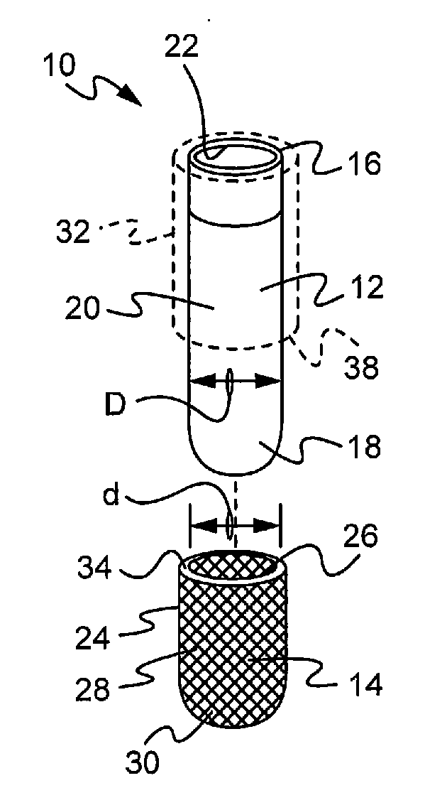
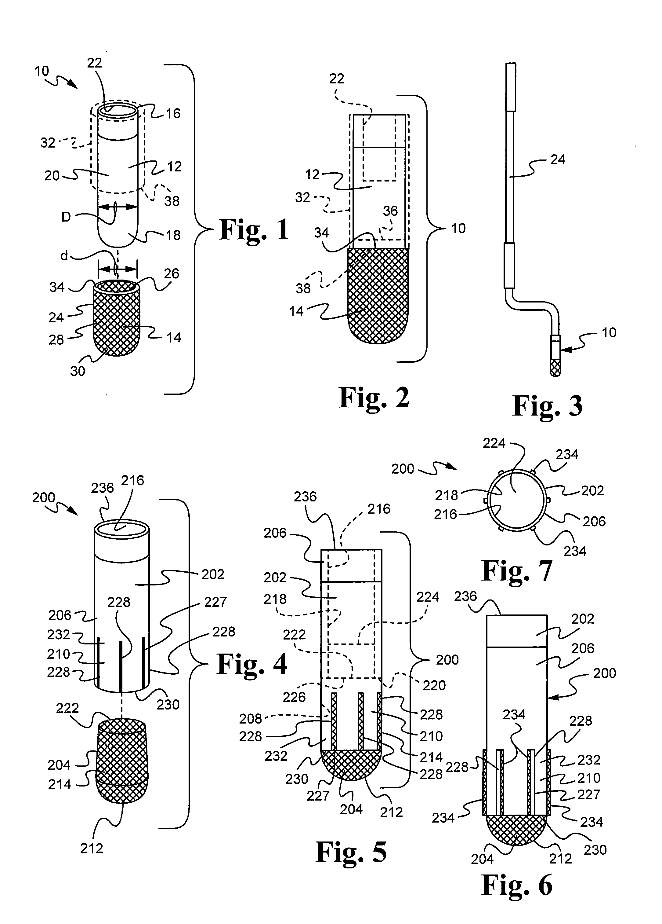
[0020]Referring to FIGS. 1-2, an implant 10 is provided for insertion into a surgical site such as a bore on bone, and in the particular examples here, into a mandible or maxilla. The implant 10 is used to support an abutment, and a prosthesis is mounted on the abutment. While two-stage endosseous implants are shown that terminate at the alveolar ridge, it will be understood that the implants may alternatively be single-stage implants with an integrally formed transgingival region or a one-piece implant with an integral abutment.

[0021]Implant 10, as well as other implants described herein, are press-fit implants and forego the use of threads as the main mechanism to engage bone. This permits these implants to be placed at a desired depth in bone by using a longitudinal driving force without the need to rotate the implant and while still forming sufficient initial stability to withstand mastication forces.

[0022]More specifically, implant 10 has a first, relatively rigid member or com...


PUM


Abstract

An expendable bone implant has a first member with a coronal end portion configured for supporting a prosthesis. A second member is at least partially porous, engages the first member, and is configured to expand outwardly upon a longitudinal force being applied to at least one of the first and second members. This anchors the implant in bone before mastication forces are applied to the implant.

Description

FIELD OF THE INVENTION[0001]The present invention relates to an implant for insertion into bone and, in particular, an expandable bone implant having improved osseointegration features.BACKGROUND OF THE INVENTION[0002]One type of bone implant is a dental implant or endosseous root form implant which is surgically implanted into a patient's upper or lower jaw to directly or indirectly anchor and support prosthetic devices, such as an artificial tooth. The implants are usually placed at one or more edentulous sites in a patient's dentition at which the patient's original teeth have been lost or damaged in order to restore the patient's chewing function. In many cases, the implant anchors a dental abutment, which in turn provides an interface between the implant and a dental restoration. The restoration is typically a porcelain crown fashioned according to known methods.[0003]The implant is usually either threaded or press-fit into a bore which is drilled into the patient's mandible or...

Claims


Application Information

Patent Timeline
Patent Type & Authority Applications(United States)
IPC IPC(8): A61C8/00
CPCA61C8/0033A61C2008/0046A61C8/0037
Inventor LOMICKA, MATTHEWVISHNUBHOTLA, SRILAKSHMIBASSETT, JEFFREY A.
Owner ZIMMER DENTAL INC
Why Eureka
Try Eureka