Image forming apparatus, pattern position determining method, and image forming system

a technology of image forming apparatus and pattern position determination, which is applied in the direction of printing, other printing apparatus, etc., can solve the problems of difficult to accurately specify the edge difficult to reflect the spotlight, and difficult to detect the voltage of the light receiving element. to be stable, so as to achieve accurate specification of the position of the test pattern

Active Publication Date: 2012-08-30
RICOH KK
View PDF2 Cites 5 Cited by
  • Summary
  • Abstract
  • Description
  • Claims
  • Application Information

AI Technical Summary

Benefits of technology

[0011]In light of the problems as described above, an object of embodiments of the present invention is to provide an image forming apparatus which adjusts an ejection timing of liquid droplets, which image forming apparatus can suppress an effect received due to characteristics of the sheet material to accurately specify a position of a test pattern.
[0013]Embodiments of the present invention make it possible to provide an image forming apparatus which adjusts an ejection timing of liquid droplets, which image forming apparatus can suppress an effect received due to characteristics of a sheet material to accurately specify a position of a test pattern.

Problems solved by technology

Moreover, it is known that, in the line head-type image forming apparatus, parallel lines are likely to appear in the sheet-conveying direction when there is a nozzle whose position of impacting is constantly offset due to a mounting error, a finishing accuracy of the nozzle, etc.
However, the correcting of the liquid droplet ejection timing as disclosed in Patent document 1 has the following problems.
As is well known, light is absorbed well by a black object, so that it is difficult for the spotlight to be reflected when the test pattern is scanned if a sheet material is white and the test pattern is black.
However, there is a problem that, when a sheet material is a material with a low reflectance (or a high transmittance), such as a tracing paper, it is difficult for a detected voltage of the light receiving element to be stable, so that the edge position of the test pattern may not be specified accurately.
In other words, for the sheet material with the low reflectance, the amplitude of the voltage value becomes small, or an amplification of sensor sensitivity or a variation in transmittance of the sheet material leads to a large variation in the voltage value, leading to instability.

Method used


Image

  • Image forming apparatus, pattern position determining method, and image forming system
  • Image forming apparatus, pattern position determining method, and image forming system
  • Image forming apparatus, pattern position determining method, and image forming system

Examples


embodiment 1

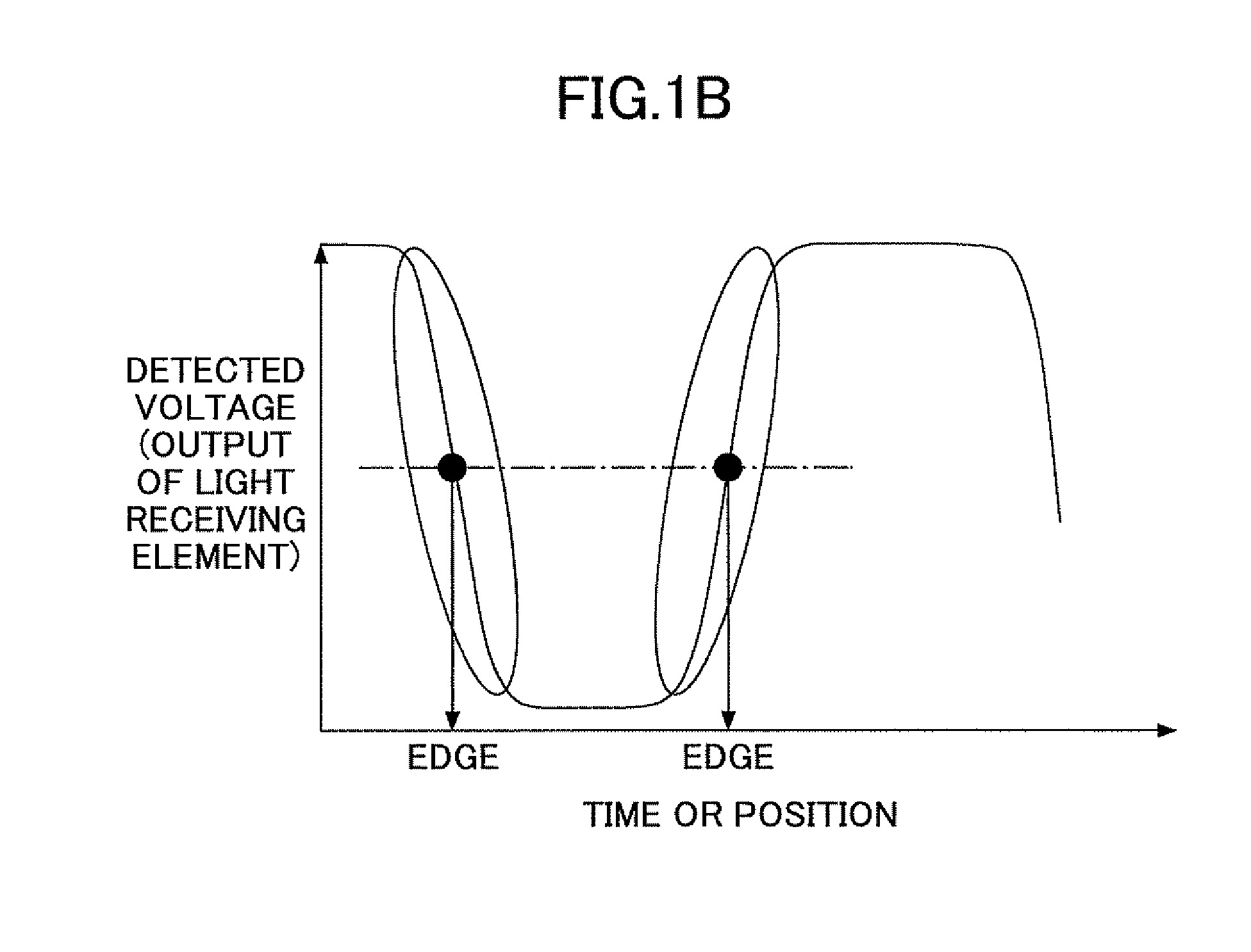
[0044]One feature of the present embodiment is performing an amplitude correction process which adjusts an amplitude relative to a detected voltage which is detected by a light receiving element.

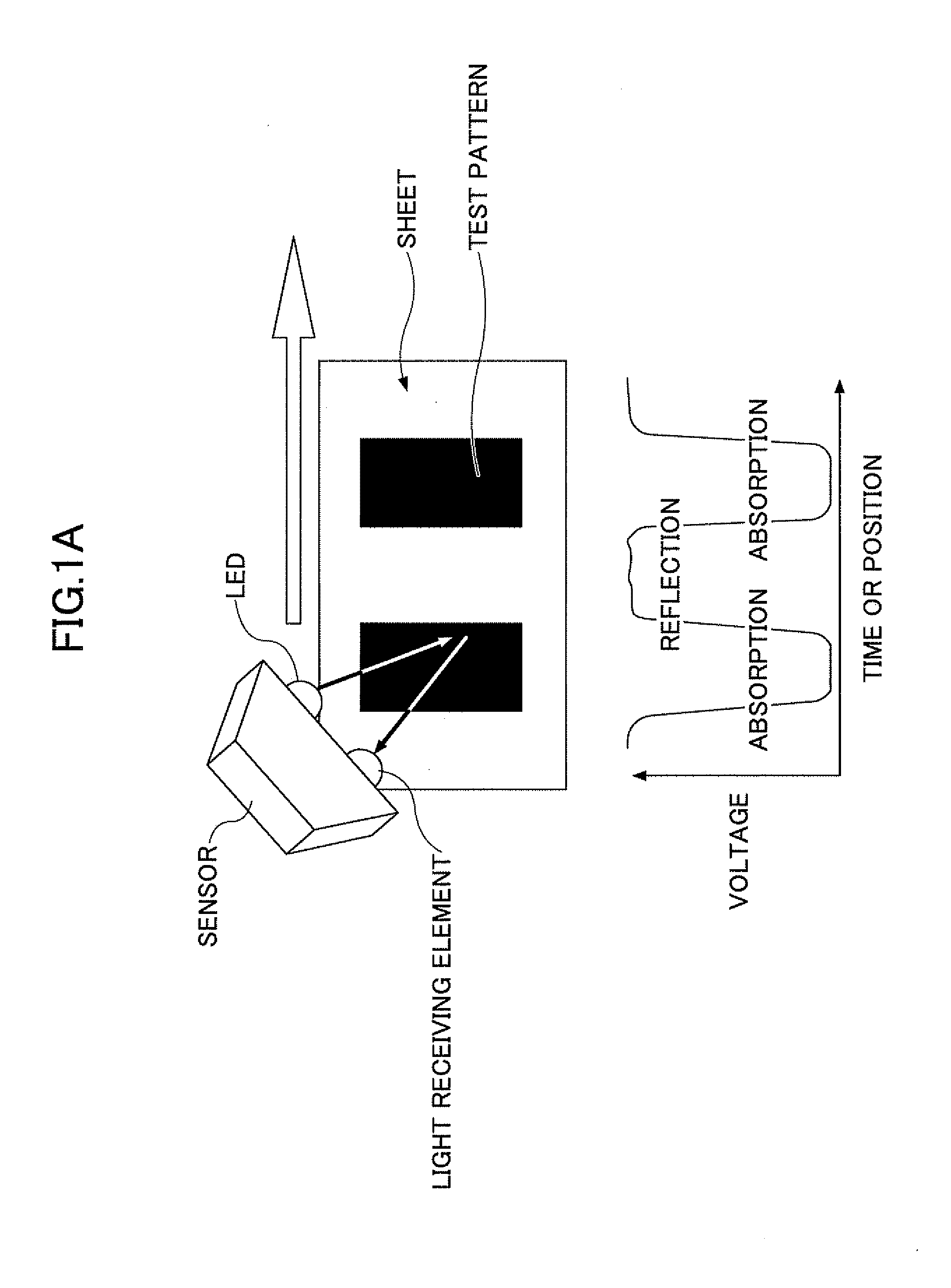
[0045]FIGS. 2A and 2B are exemplary diagrams which schematically illustrate a light emitting element, a light receiving element, and a sheet material. FIG. 2C shows an example of a detected voltage Vs2 of a sheet material with a low reflectance, such as a tracing paper, etc., while FIG. 2D shows an example of a detected voltage Vs1 of a tracing paper on which a test pattern is formed. As shown in FIG. 2C, when a spotlight scans a sheet material with a low reflectance (a high transmittance) as shown in FIG. 2C, the detected voltage becomes unstable. Moreover, when the spotlight scans the sheet material on which the test pattern is formed, the detected voltage is unstable even though the instablity is not likely to be noticeable due to an occurrence of a local maximum value and a local minimum...

embodiment 2

[0244]In the present embodiment, an amplitude correction process is described for an image forming system embodied by a server, not an image forming apparatus.

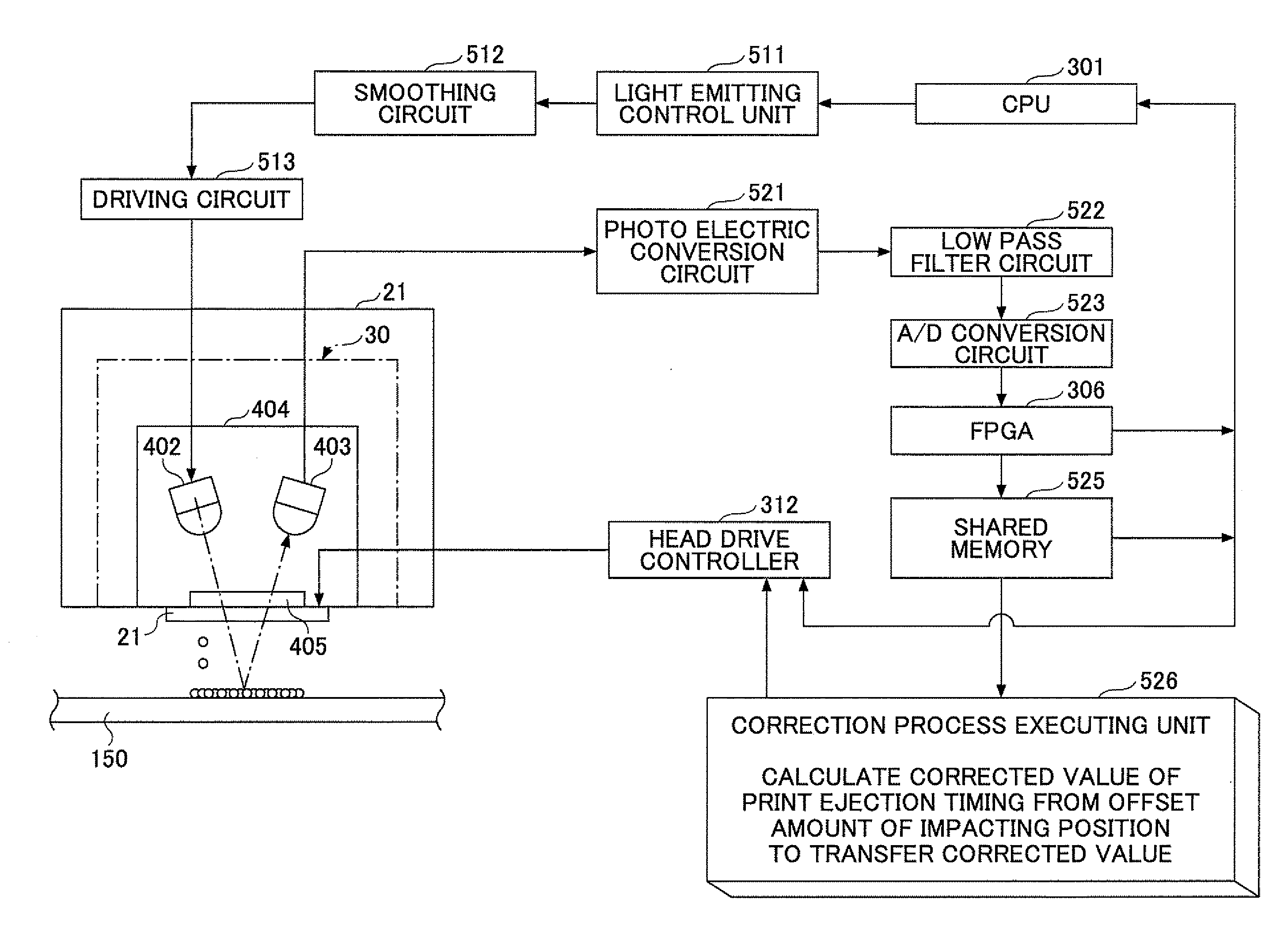
[0245]FIG. 25 is an exemplary diagram which schematically describes an image forming system 500 which has an image forming apparatus 100 and a server 200. In FIG. 25, the same letters are given to the same elements as FIG. 3, so that a repeated explanation is omitted. The image forming apparatus 100 and the server 200 are connected via a network 201, which includes an in-house LAN; a WAN which connects the LAN; or the Internet, or a combination thereof.

[0246]In the image forming system 500 as in FIG. 25, the image forming apparatus 100 forms a test pattern and scans the test pattern by a print position offset sensor, and the server 200 calculates the correction value of the liquid droplet ejection timing. Therefore, a processing burden of the image forming apparatus 100 may be reduced and functions of calculating a correction ...


PUM


Abstract

An image forming apparatus is disclosed which reads a test pattern, including a reading unit, a relative movement unit, a second detected data obtaining unit which obtains one or more second detected data sets of a reflected light which is received from a scanning position of a light by a light receiving unit while the reading unit moves relatively with respect to the recording medium before the test pattern is formed, a first detected data obtaining unit which obtains one or more first detected data sets of the reflected light which is received by the light receiving unit when the light moves over the test pattern at generally the same scanning position as the scanning position while the reading unit moves relatively with respect to the recording medium after the test pattern is formed, and a signal correction unit.

Description

TECHNICAL FIELD[0001]The present invention generally relates to liquid-ejecting image forming apparatuses and more specifically relates to an image forming apparatus which can correct an offset of an impacting position of liquid droplets.BACKGROUND ART[0002]Image forming apparatuses (below called liquid ejecting image forming apparatuses) are known which eject liquid droplets onto sheet material such as a sheet of paper to form an image. The liquid ejecting image forming apparatuses may generally be divided into a serial-type image forming apparatus and a line-head type image forming apparatus. In the serial-type image forming apparatus, a recording head moves in both main scanning directions perpendicular to a direction of sheet conveying while the sheet conveying is repeated to form an image over the sheet of paper. In the line head-type image forming apparatus with nozzles being aligned in a length which is almost the same length as a maximum width of the sheet of paper, when a t...

Claims


Application Information

Patent Timeline
Patent Type & Authority Applications(United States)
IPC IPC(8): B41J29/393
CPCB41J2/2132
Inventor HORIKAWA, DAISAKUYORIMOTO, MAMORUOKADA, TATSUHIKOMORIWAKI, MAKOTO
Owner RICOH KK
Why Eureka
Try Eureka