Slag remover for discharging combustion residues of an incineration plant

a technology of incineration plant and slag remover, which is applied in the direction of combustion type, combustion process, lighting and heating apparatus, etc., can solve the problems of load torque generation, shaft, load torque generation, unfavorable optimal force transmission, etc., and achieve optimal force transmission and avoid generation of load torque

Active Publication Date: 2013-02-28
HITACHI ZOSEN INOVA AG
View PDF13 Cites 3 Cited by
  • Summary
  • Abstract
  • Description
  • Claims
  • Application Information

AI Technical Summary

Benefits of technology

The present invention is about a slag remover for a manufacturing process that eliminates the generation of load torcules and allows for optimal force transmission to the push rams. The slag remover is designed with a single drive lever and a single cylinder-piston unit, which reduces the need for adjusting various cylinder piston units or monitoring them during operation. The shaft is mounted in bearing pedestals that can be easily detached, and the drive lever and output levers can be welded to the shaft for high mechanical stability. The invention also allows for easy removal of the shaft or levers by detaching the bearing pedestals. These features make the slag remover easy to operate, remove and adjust.

Problems solved by technology

A drawback with such a slag remover is that, for instance, when slag is present which is conveyable only with great effort and this is distributed inhomogeneously over the trough cross section, load torques, which necessitate appropriate dimensioning of the shaft, are generated.
Moreover, the moments of force which act on the respective bearing are in this slag remover relatively large, which is not conducive to optimal force transmission.
However, as a result of the accompanying weakening of the shaft or lever arm, the mechanical stability thereof is impaired.
Moreover, the fitting of keyways or corresponding keys is relatively complex and expensive.
The problems with respect to the generation of load torques in the shaft persist, however.

Method used


Image

  • Slag remover for discharging combustion residues of an incineration plant
  • Slag remover for discharging combustion residues of an incineration plant
  • Slag remover for discharging combustion residues of an incineration plant

Examples


Embodiment Construction

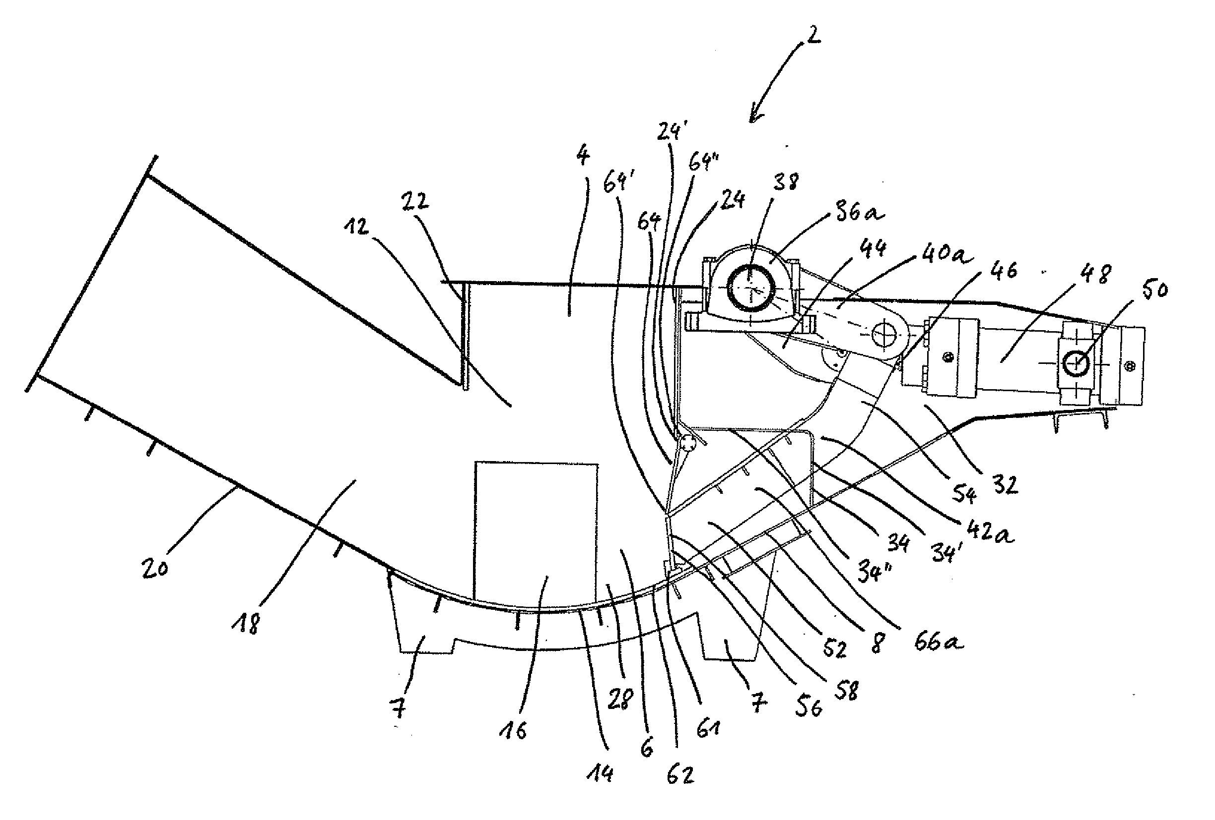
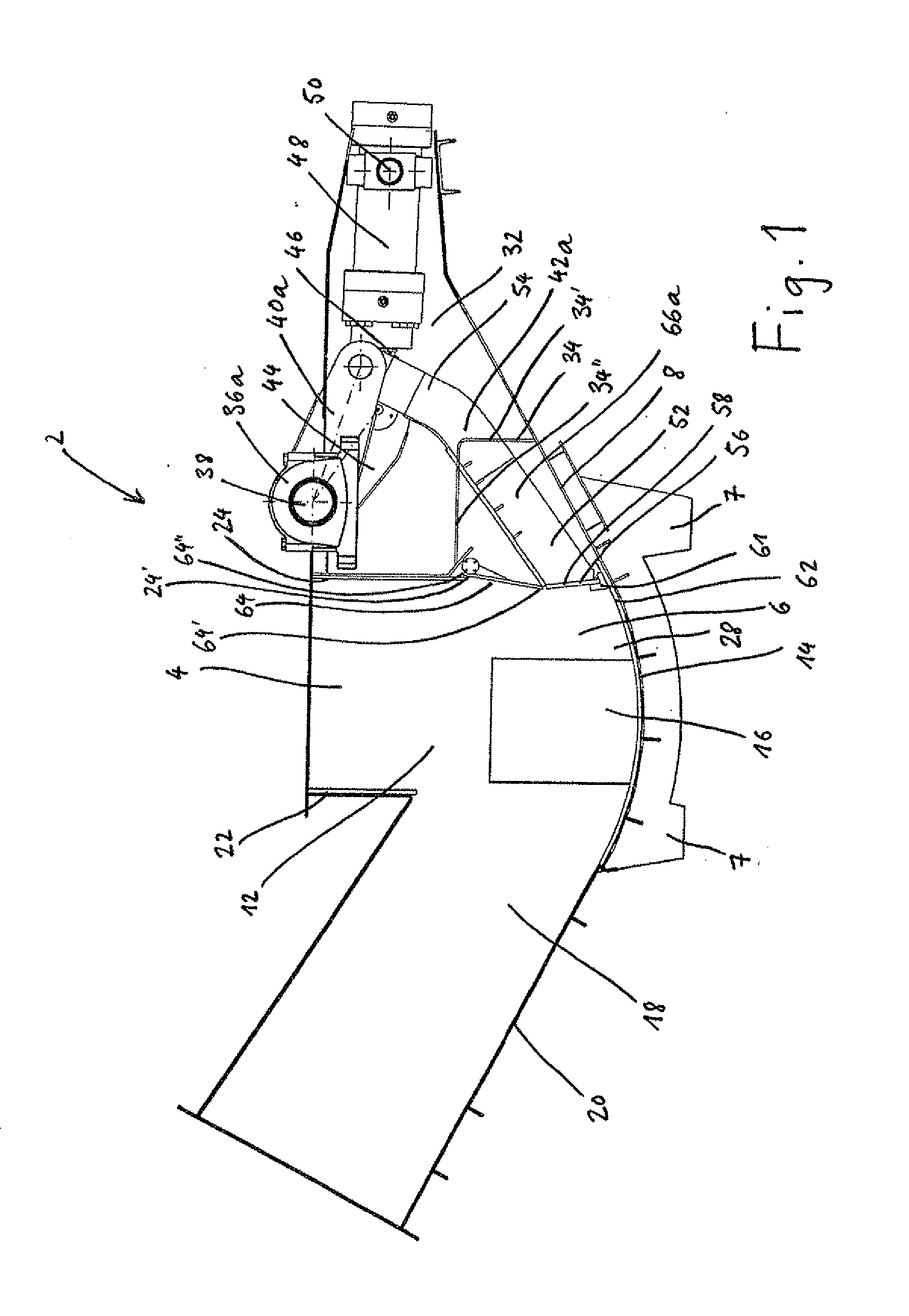
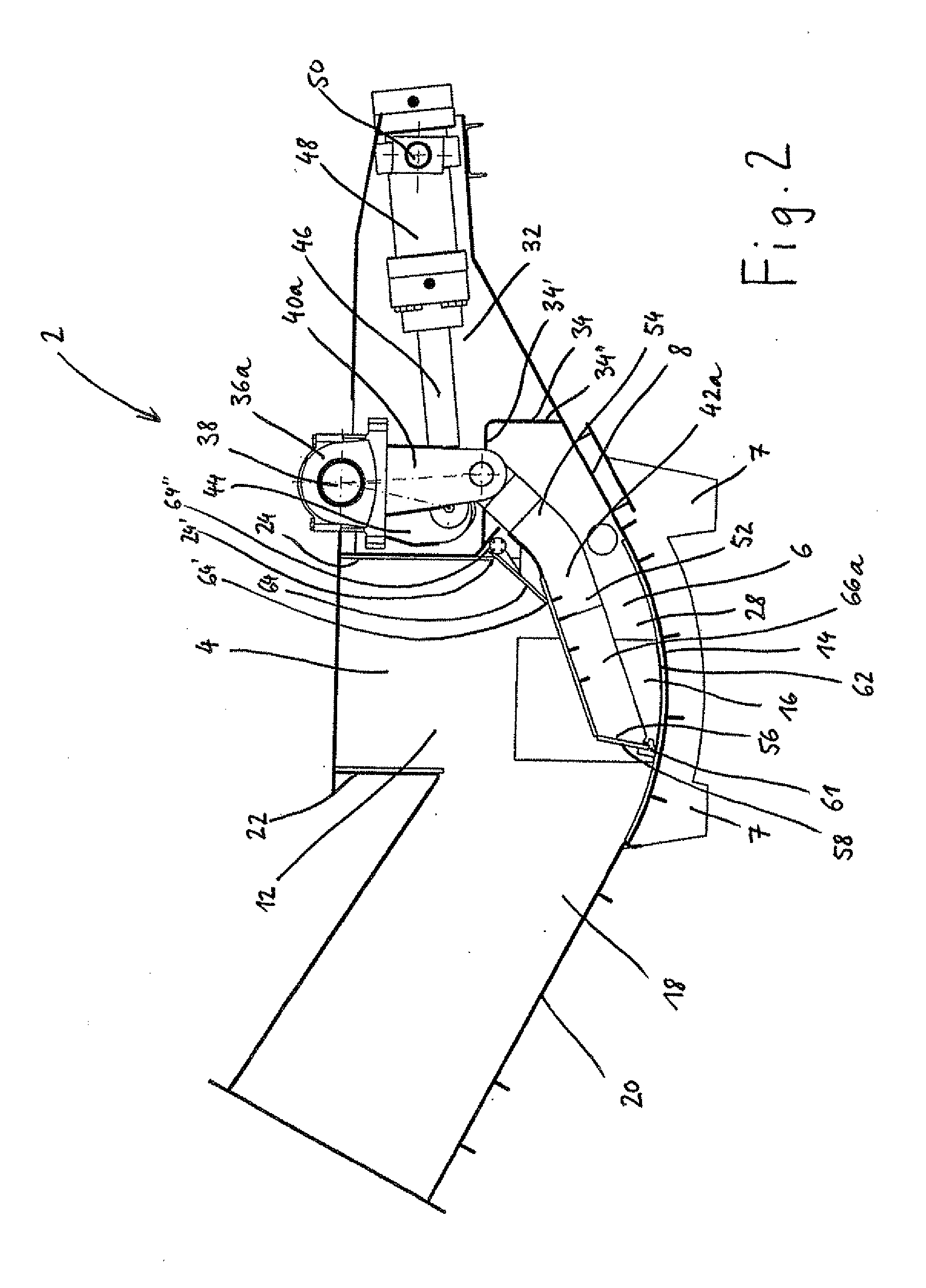
[0035]The slag remover 2 shown in FIG. 1 is generally disposed in the region of the outlet of a combustion chamber (not represented) of an incineration plant. From the combustion grate of the combustion chamber, the non-combustible combustion residues (slag) fall into a vertically running drop shaft 4, which can flare out in the shape of a funnel in the direction of the outlet of the combustion chamber.

[0036]The drop shaft 4 opens out into a water-filled trough 6, which is disposed on a supporting structure having appropriate pillars 7 and extends in a longitudinal direction running at right angles to the orientation of the drop shaft 4. In this trough 6 are collected the combustion residues falling through the drop shaft 4. The trough 6 has a trough housing 8 comprising two side walls 10a, 10b, which define the trough width and respectively run parallel to the longitudinal direction in a vertical plane, and a trough bottom 14, which is arched below the drop shaft mouth 12. In the s...


PUM


Abstract

A slag remover for discharging combustion residues of an incineration plant comprises a trough, which has a trough housing having two side walls, which define the trough width, and having a trough bottom, and which is intended to collect the combustion residues evacuated from a combustion chamber of the incineration plant. The trough further comprises at least two push rams for pushing the combustion residues out of the trough, and a shaft rotatably mounted in two shaft bearings and on which at least one drive lever cooperating with a cylinder-piston unit and at least two output levers connected to respectively one of the push rams are disposed in a rotationally secure manner. The cylinder-piston unit is here designed such that the push rams move back and forth between a retracted position and an extended position. The drive lever is disposed between two output levers.

Description

INTRODUCTION[0001]The present invention relates to a slag remover for discharging combustion residues of an incineration plant, and to the use of the slag remover for a waste incineration plant.BACKGROUND[0002]In the field of waste incineration , slag removers serve to discharge from the incineration plant, in the course of the incineration, the residues (slag) which cannot be further incinerated.[0003]Slag removers generally comprise a drop shaft, via which the combustion residues fall from the combustion chamber into a water-filled trough. From this, the combustion residues are pushed by means of a push ram over an expulsion chute or expulsion path, whence they can be transported onward in dumpable form.[0004]One example of a slag remover is described, for instance, in DE-A-2539615. Here a discharge piston, which pushes into the expulsion chute the slag which falls onto the trough bottom, is articulately connected at its rear end to one or more thrust cranks, which are seated in a...

Claims


Application Information

Patent Timeline
IPC IPC(8): F23J1/06
CPCF23J1/02F23J2900/01021F23J2700/003
Inventor BRENNWALD, WERNER
Owner HITACHI ZOSEN INOVA AG
Why Eureka
Try Eureka