

Cage rotor for an asynchronous machine and method for producing the cage rotor
a cage rotor and asynchronous machine technology, applied in the direction of synchronous motors, stator/rotor bodies, solid insulation, etc., can solve the problems of fatigue and/or creep, and achieve the effect of optimizing electromagnetic properties, high electromagnetic efficiency of the cage rotor, and optimizing electrical properties
- Summary
- Abstract
- Description
- Claims
- Application Information
AI Technical Summary
Benefits of technology
Problems solved by technology
Method used
Image

Examples
Embodiment Construction
[0002]The invention relates to a cage rotor for an asynchronous machine and to a method for producing the cage rotor.
BACKGROUND OF INVENTION
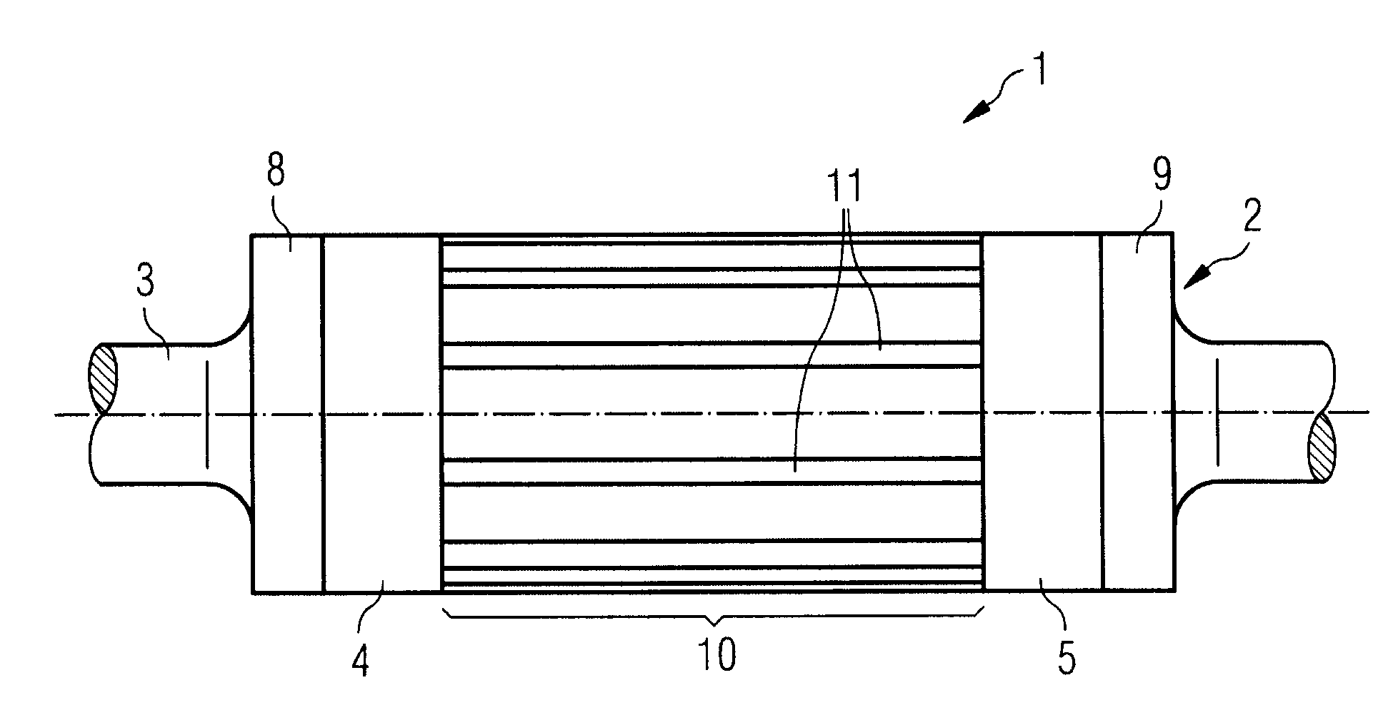
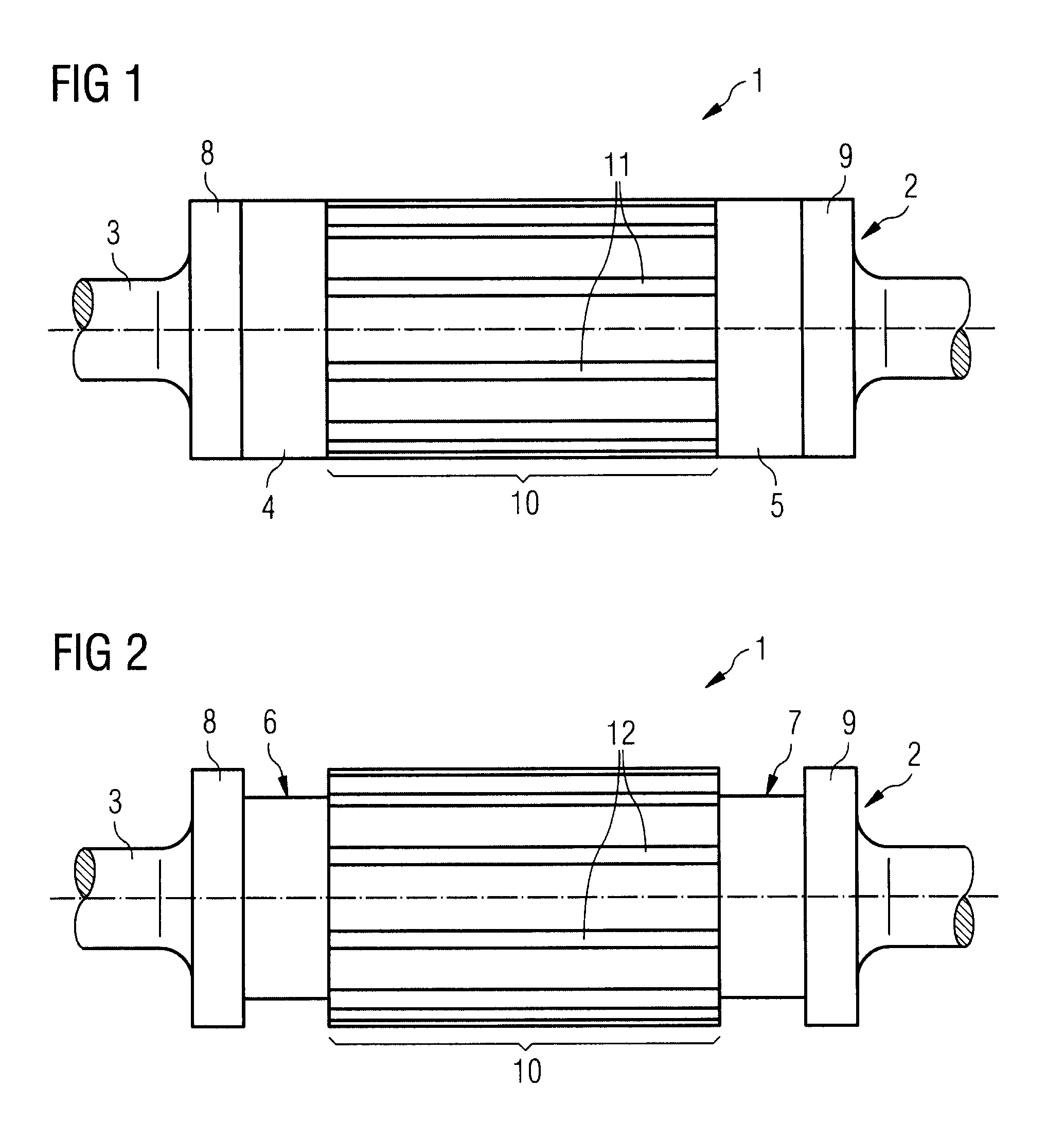
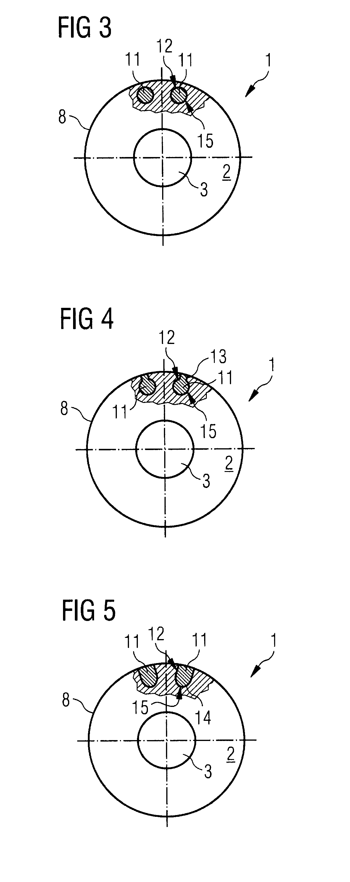
[0003]An asynchronous machine, such as for example an asynchronous motor or an asynchronous generator, has a cage rotor with a plurality of conductor bars, which are arranged lying next to one another on the circumference of the cage rotor and extending in the axial direction. At their longitudinal ends, the conductor bars are connected to one another in an electrically conducting manner respectively by a short-circuiting ring. In the case of asynchronous machines from a certain power class, circumferential speeds that may be around 250 m / s occur at the cage rotor. With these high circumferential speeds, the strength of the cage rotor has to meet particular requirements, it being known to form the cage rotor with a solid type of construction. The cage rotor has a rotor body, which has longitudinal slots which are distributed uniformly over the c...
PUM
| Property | Measurement | Unit |
|---|---|---|
| circumferential speeds | aaaaa | aaaaa |
| adhesion | aaaaa | aaaaa |
| circumference | aaaaa | aaaaa |
Abstract
Description
Claims
Application Information