Gland plate

Inactive Publication Date: 2013-06-27
TRELLEBORG INDAL PRODS FINLAND
View PDF5 Cites 7 Cited by
  • Summary
  • Abstract
  • Description
  • Claims
  • Application Information

AI Technical Summary

Benefits of technology

The invention is a new type of cable gland plate that can be flexible fitted for different applications. It is less expensive to manufacture and is easy to handle and seal in difficult installations. The plate can be adapted for different lead-through sizes and provides a simple and easy-to-use solution. The pressure forces used in the invention are strictly controlled, which allows the plate to be made light and small-sized, reducing manufacturing costs. Overall, the invention simplifies the installation process and improves efficiency.

Problems solved by technology

However, even the plate illustrated in FIG. 1 is problematic.
However, the applications are unique, so the sizes of the cables may vary in such a way that a lead-through of a suitable size for all cables may not be found from one plate in a specific application.
However, the structure has been developed for heavy industrial use and is not applicable for example to pass through electric and data transfer cables in electrical enclosures and equivalent applications.
The gland plate must be constructed one gland unit at a time, whereby a work project including many small cables is slow to carry out.
In addition, the structure must be made heavy and large to be able to stay in the correct shape and hence tight.

Method used


Image

  • Gland plate
  • Gland plate
  • Gland plate

Examples


Embodiment Construction

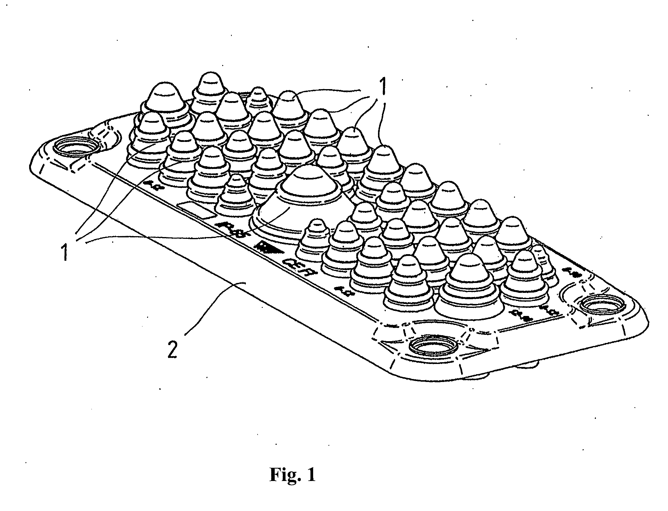
[0027]FIG. 1 illustrates the traditional cable gland plate having a large number of cups 1 of different sizes functioning as cable glands and mounted to a common frame 2. This way, they form one integral assembly.

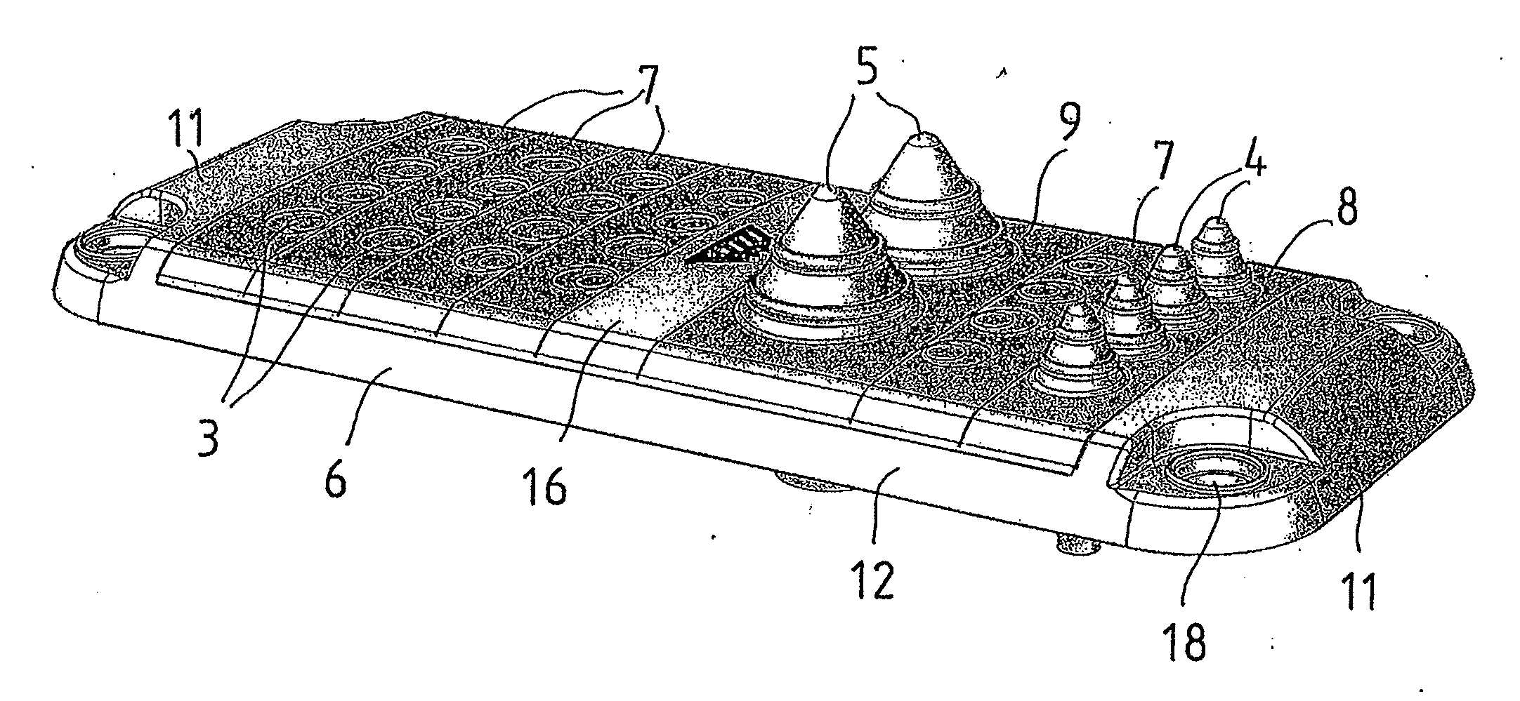
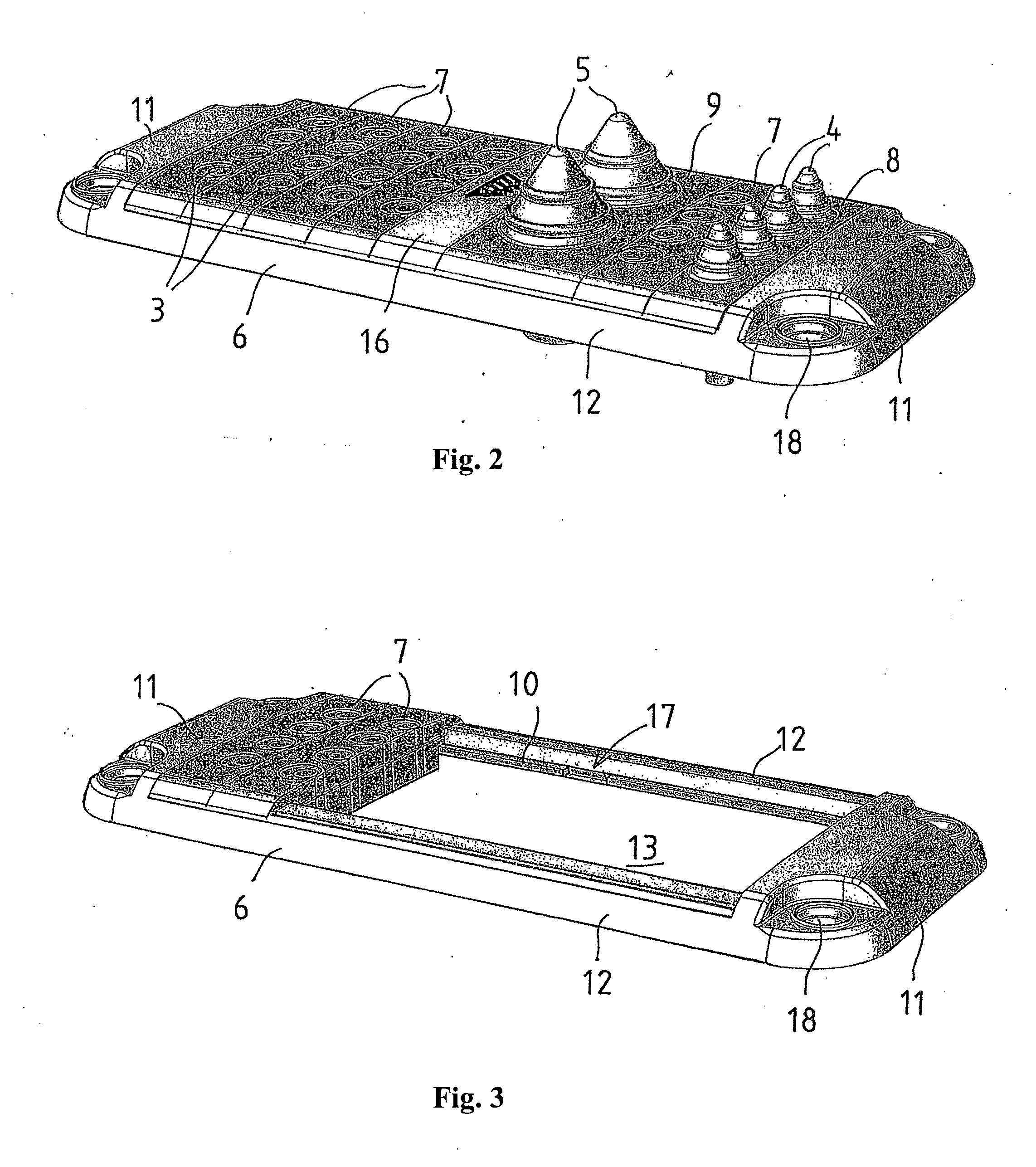
[0028]FIG. 2 illustrates one cable gland plate according to the invention. It includes a substantially rectangular rigid frame 6 having mounting holes 18 at the corners thereof. The frame is formed by end blocks 11 and by edge beams 12 connecting them. Supported between the end blocks 11 against the edge beams 12 is a set of gland elements 7,8,9. The first gland elements 7, there being five of them, have four planar lead-throughs 3 in a row designed for relatively thin cables or lines. The second gland element 8 has four conical lead-throughs 4 in a row designed for slightly larger cables. The third gland element 9 has only two conical lead-throughs 5 designed for clearly larger cables.

[0029]The width of the elements, i.e. the dimension thereof in the lengthwise direction o...


PUM


Abstract

The invention relates to a cable gland plate for passing cables in a sealed fashion through a casing, such as the wall of a low voltage switchgear. The cable gland plate includes a substantially rectangular rigid frame (6) and, a set of gland elements (7,8,9) and a pressure unit (16). According to the invention, one pair of opposed edges (12) of the rigid frame includes slide bars (10); one pair of opposed edges of each gland element (7,8,9) includes slide posts (14) arranged to be fitted to the opposed slide bars; and the pressure unit (16) includes an actuator (35) carrying out two sequential pressure actions in such a way that the first pressure action presses the gland elements to each other in the lengthwise direction of the slide bars, and the second pressure action pushes the pressure unit against the frame and the adjacent gland elements.

Description

FIELD OF THE INVENTION[0001]The invention relates to the cable gland plate defined in the preamble of claim 1.BACKGROUND OF THE INVENTION[0002]The known cable gland plates designed for several cables have a plate-type body with a set of holes, always one hole for one cable to be passed therethrough. The holes are covered or sealed with an elastic film, a rubber casing, which is to be punctured to push the cable through the hole, whereby the film becomes sealed against the surface of the cable due to the elasticity thereof, this way sealing the lead-through. One such known gland plate is illustrated in FIG. 1. The elastic films may be straight or, as illustrated in the figure, conical cups 1, and, in general, there are as many of them in the gland plate as is possible to accommodate on the surface thereof. Also, second seals may be disposed on the other surface of the plate in alignment with the lead-throughs, whereby double seals are obtained for the cables. In general, one of the s...

Claims


Application Information

Patent Timeline
IPC IPC(8): H02G15/013
CPCH02B1/305H02G15/013H02G3/22
Inventor NURMI, AAPOHAUTAMAKI, MIKA
Owner TRELLEBORG INDAL PRODS FINLAND
Why Eureka
Try Eureka