Motor having a braking function and used in linear actuator

a technology of linear actuators and braking functions, which is applied in mechanical energy handling, mechanical equipment, mechanical energy handling, etc., can solve the problems of reducing the life of the helical spring, the contact area between the helical spring and the cylindrical ring is not large enough to generate a sufficient decelerating effect or braking effect, etc., to achieve better braking and decelerating effect, prolong the life, and improve the effect of braking

Active Publication Date: 2013-07-04
TIMOTION TECH CO LTD
View PDF2 Cites 17 Cited by
  • Summary
  • Abstract
  • Description
  • Claims
  • Application Information

AI Technical Summary

Benefits of technology

[0010]The present invention has advantageous features as follows. Since the wear of the helical spring is small, its lifetime is extended. The contact area between the braking ring and the rotation shaft is large enough to generate a better braking and decelerating effect. The braking means and the stopping means are disposed on the rotation shaft of the linear actuator, so that only a small force is needed to generate a better braking effect. When the telescopic tube retracts, a braking and decelerating effect is obtained. Thus, the telescopic tube can be kept at a stable rate to lower or retract into an outer tube, thereby making a user to feel more comfortable. Further, the present invention has other advantages of simple structure, low cost, and small volume. With the rectangular structure of the braking ring and / or one end of the helical spring being fixed, the braking ring and the helical spring will not rotate relative to each other, so that each curved plate can generate a better braking effect to the rotation shaft.

Problems solved by technology

Or, the helical spring may be worn quickly to reduce its lifetime.
Thus, the contact area between the helical spring and the cylindrical ring is not large enough to generate a sufficient decelerating effect or braking effect.

Method used


Image

  • Motor having a braking function and used in linear actuator
  • Motor having a braking function and used in linear actuator
  • Motor having a braking function and used in linear actuator

Examples


Embodiment Construction

[0028]The detailed description and technical contents of the present invention will become apparent with the following detailed description accompanied with related drawings. It is noteworthy to point out that the drawings is provided for the illustration purpose only, but not intended for limiting the scope of the present invention.

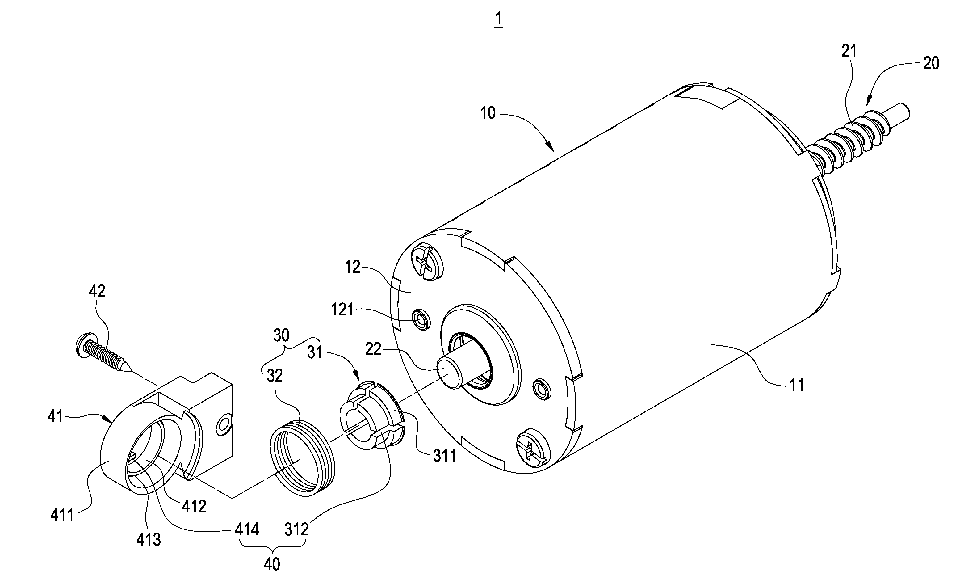
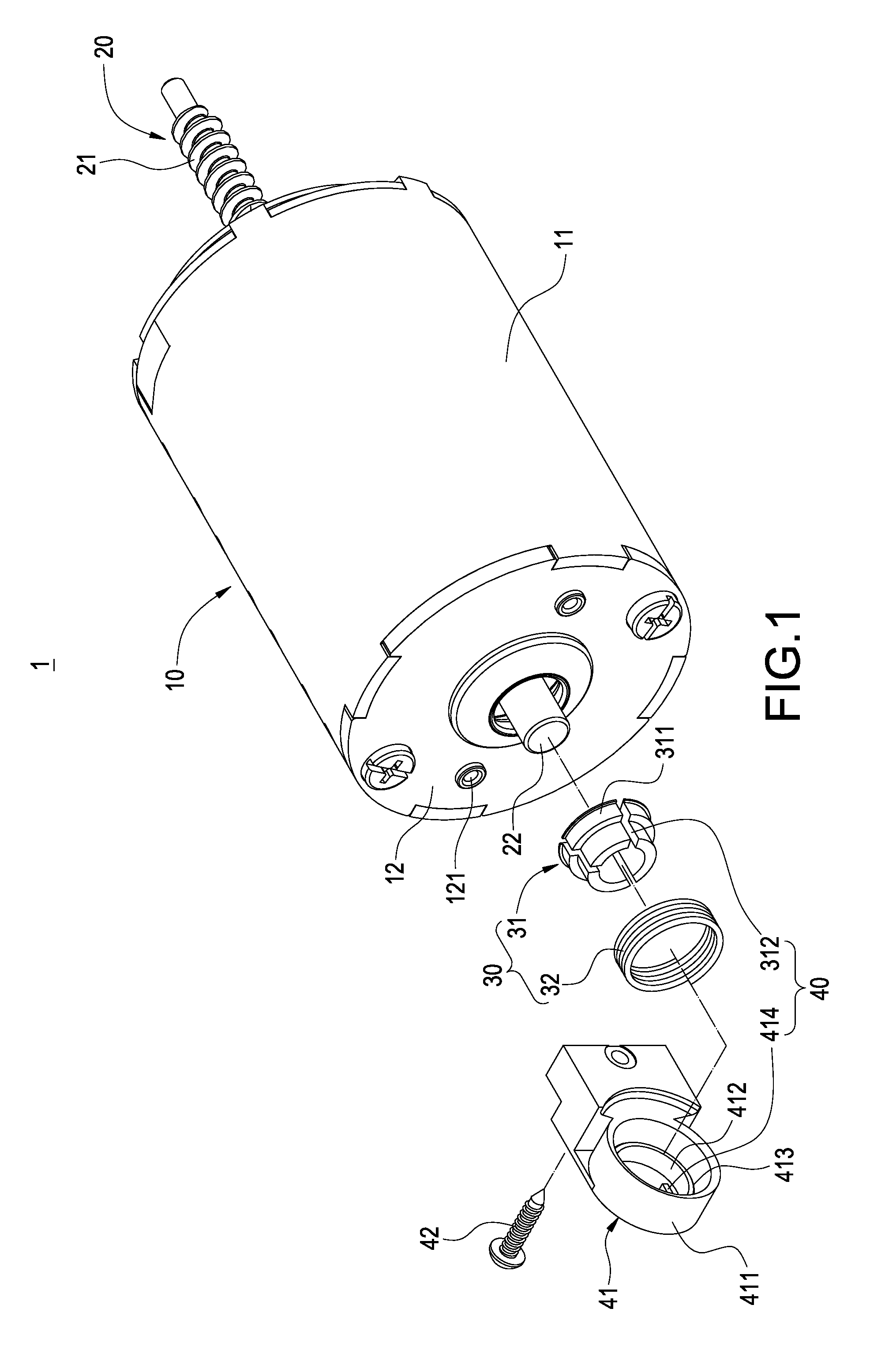
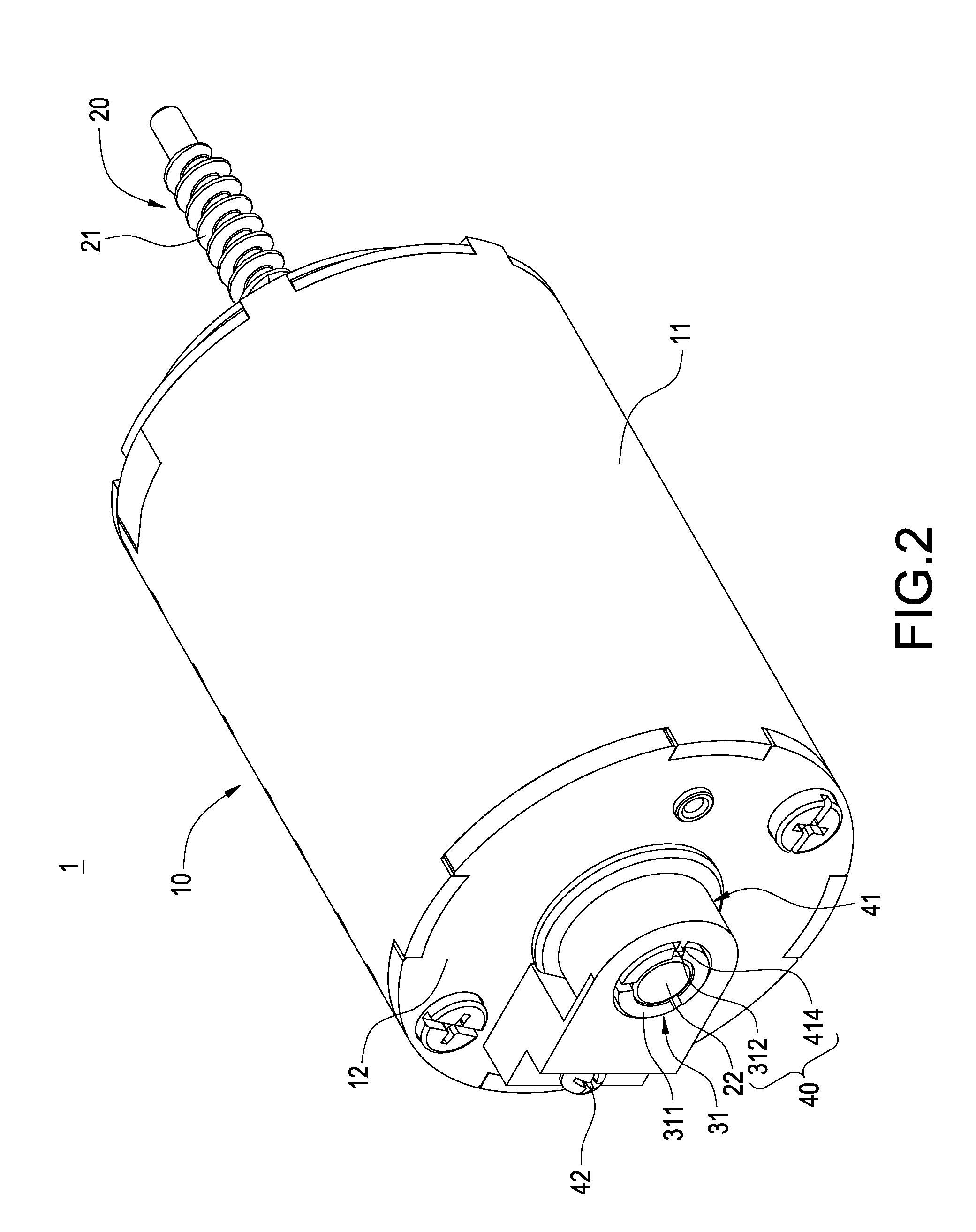
[0029]Please refer to FIGS. 1 to 3. The present invention provides a motor having a braking function and used in a linear actuator. The motor 1 includes a main body 10, a rotation shaft 20, a braking means 30, and a stopping means 40.

[0030]The main body 10 has a cylindrical casing 11. The interior of the casing 11 is provided with a stator, a rotor, a winding or the like (not shown). An end surface of the casing 11 is provided with an end cover 12. The end cover 12 is provided with a plurality of threaded holes 121.

[0031]The rotation shaft 20 penetrates the center of the main body 10. Both ends of the rotation shaft 20 extend outwardly to be exposed to t...


PUM


Abstract

The present invention provides a motor having a braking function and used in a linear actuator. The motor includes a main body, a rotation shaft, a braking means and a stopping means. The rotation shaft penetrates the center of the main body. The braking means includes a braking ring and a helical ring. The braking ring includes a plurality of curved plates. The helical ring surrounds outer edges of the curved plates. Each curved plate is put on the outer periphery of the rotation shaft. The stopping means is disposed between the main body and the braking means for restricting the rotation of any of the curved plates. By this arrangement, a better braking and decelerating function can be achieved.

Description

BACKGROUND OF THE INVENTION[0001]1. Field of the Invention[0002]The present invention relates to a motor used in a linear actuator, and in particular to a motor having a braking function and used in a linear actuator.[0003]2. Description of Prior Art[0004]Linear actuator employs a motor, a worm rod, a worm wheel and other driving elements to drive a lead screw to rotate. The lead screw drives a telescope tube threadedly connected onto the lead screw to generate a linear extending action or retracting action. Since the structure and installation of the linear actuator are easier and more convenient than those of a pneumatic cylinder or a hydraulic cylinder, the linear actuator has been widely used in a sickbed, electric chair or other places where extending and retracting actions are needed.[0005]EP0662573B1 and WO2004-027290A2 disclose a linear actuator respectively. The linear actuator disclosed in EP0662573B1 includes a worm rod, a lead screw, a worm wheel set fixed to one end of ...

Claims


Application Information

Patent Timeline
Patent Type & Authority Applications(United States)
IPC IPC(8): H02K7/102
CPCH02K7/102H02K7/1166H02K7/14F16D49/02F16H25/2454F16H2025/209A61G7/018F16H25/22H02K7/116
Inventor WU, CHOU-HSIN
Owner TIMOTION TECH CO LTD
Why Eureka
Try Eureka