Radar device

a radar and target technology, applied in the field of radar devices, can solve the problems of deterioration of detection accuracy of radar devices when they detect targets in a long distance, and large amount of frequency resources, so as to reduce interference and low range sidelobe characteristics

Active Publication Date: 2013-07-11
PANASONIC INTELLECTUAL PROPERTY MANAGEMENT CO LTD
View PDF9 Cites 26 Cited by
  • Summary
  • Abstract
  • Description
  • Claims
  • Application Information

AI Technical Summary

Benefits of technology

[0042]According to the radar device of the invention, it is possible to maintain low range sidelobe characteristics in a signal of a reflected wave from a target and to reduce interference between a plurality of sector radars even in a case where the target moves.

Problems solved by technology

In this case, detection accuracy when the radar device detects the target in a long distance may be deteriorated.
In a case where the interference occurs, the wide area radar device in the related art causes a problem that position measurement estimation accuracy of the target is deteriorated.
According to the first method, it is possible to suppress the occurrence of interference between the respective sector radars by using the different frequency bands, but the following problem arises.
That is, in the former case where the plurality of different frequency bands is used, there is a problem that a large amount of frequency resources are necessary.
Further, in the latter case where the frequency bands of the narrow band are used, there is a problem that time resolution of position measurement estimation (corresponding to distance resolution) of a target in each sector radar is reduced.
However, in a case where the transmission signal passes through CDM for each sector radar for transmission, the transmission signal is asynchronously received from a different sector radar, and as a result, interference between codes occurs between the respective sector radars.
Further, in general, an auto-correlation characteristic of a code sequence having low cross-correlation is not superior, and as a result, a range sidelobe becomes large.
Thus, in the radar device in the related art, there is a problem that detection performance is deteriorated in a case where a mixed signal of a plurality of reflected waves from a target present in a short distance and a target present in a long distance is separated to detect each target.

Method used


Image

  • Radar device
  • Radar device
  • Radar device

Examples


first embodiment

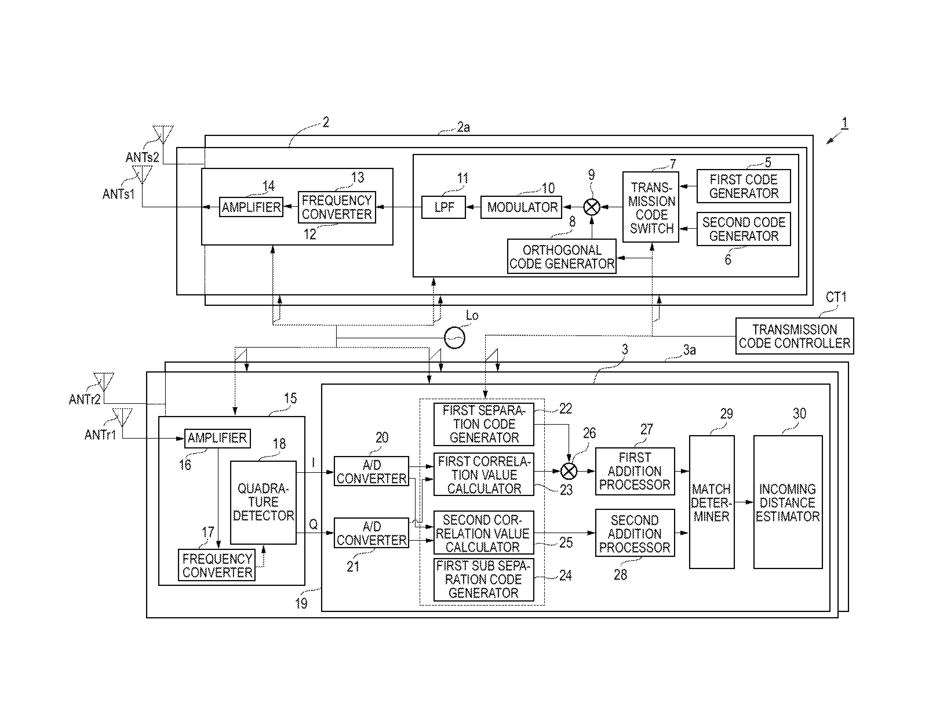
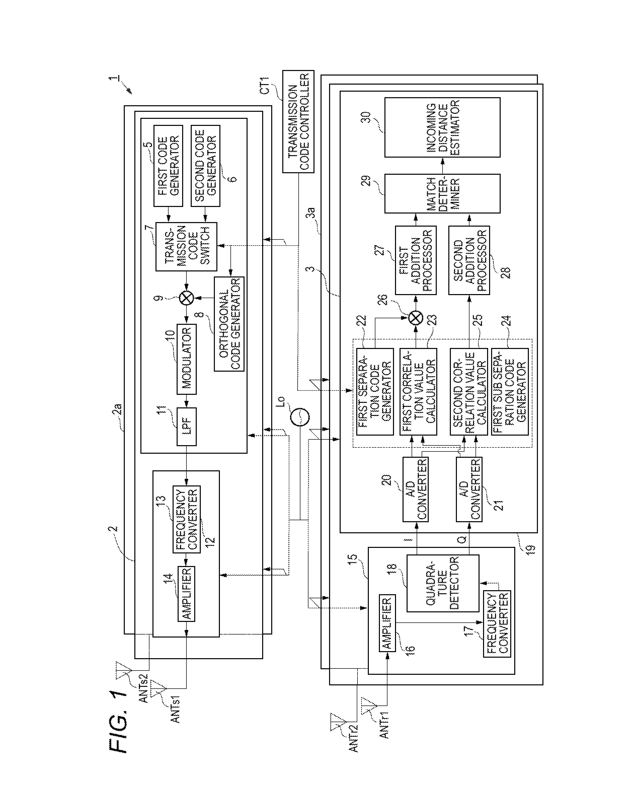
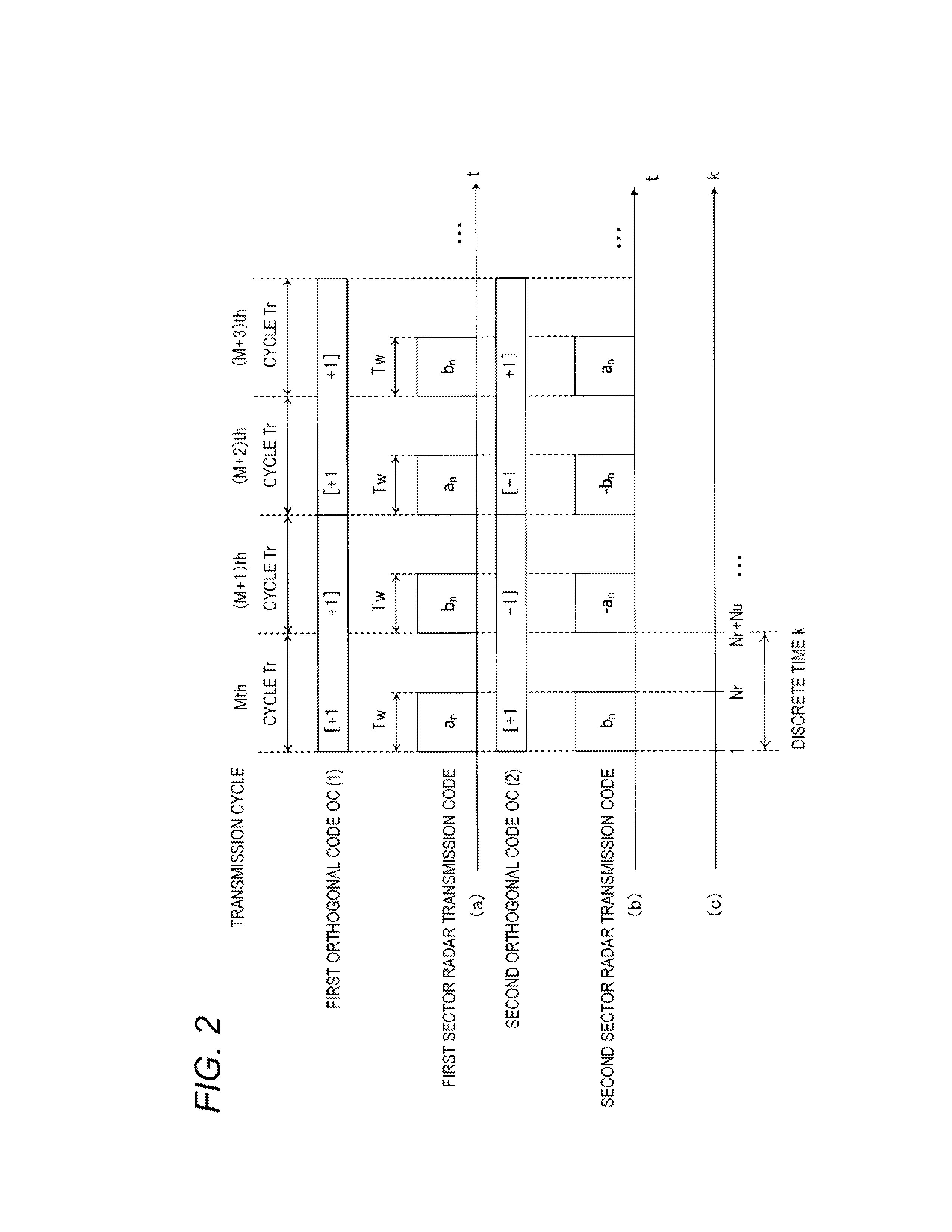
[0058]A configuration and an operation of a wide area radar device 1 according to a first embodiment will be described with reference to FIG. 1 and FIG. 2. FIG. 1 is a block diagram illustrating an internal configuration of the wide area radar device 1 according to the first embodiment. FIG. 2 is a timing chart relating to the operation of the wide area radar device 1 according to the first embodiment. (a) in FIG. 2 is a diagram illustrating a first orthogonal code OC (1) and a transmission code of a first sector radar at each transmission cycle Tr, (b) in FIG. 2 is a diagram illustrating a second orthogonal code OC (2) and a transmission code of a second sector radar at each transmission cycle Tr, and (c) in FIG. 2 is a diagram illustrating the relationship between each transmission cycle Tr and a discrete time k.

[0059]As shown in FIG. 1, the wide area radar device 1 includes a reference signal oscillator Lo, a transmission code controller CT1, a first sector radar transmitter 2 to...

modification example 1

of the First Embodiment

[0226]The complementary codes a, and bn having the code length L used in the first embodiment is obtained by recursive connection from sub codes that form a pair of complementary codes having a code length L / 2w. Thus, in a sub separation code subOC (q) generated according to code units en and fn having a code length L / 2w, the orthogonal relationship is obtained. Here, w represents an integer of 1 or more.

[0227]Accordingly, the wide area radar device according to Modification Example 1 of the first embodiment may generate a sub separation code using the pair of sub codes e and fn having the code length L / 2w that is a shorter code length, according to the movement speed of the target.

[0228]In this case, the second correlation value calculator of the wide area radar device performs a second correlation calculation in a unit obtained by dividing a portion corresponding to the transmission section Tw of the reference transmission signal r(k, M+p) by 2w as a referen...

modification example 2

of the First Embodiment

[0232]In the first embodiment, the wide area radar device 1 has the two sector configuration of the first sector radar and the second sector radar as shown in FIG. 1. A wide area radar device according to Modification Example 2 of the first embodiment further includes a third sector radar, and thus, has a configuration of total three sector radars.

[0233]FIG. 7 and FIG. 8 are timing charts relating to operations of the wide area radar device of Modification Example 2 according to the first embodiment. FIG. 7(a) and FIG. 8(a) are diagrams illustrating an orthogonal code OC (1) and a transmission code of a first sector radar at each transmission cycle Tr. FIG. 7(b) and FIG. 8(b) are diagrams illustrating an orthogonal code OC (2) and a transmission code of a second sector radar at each transmission cycle Tr. FIG. 7(c) and FIG. 8(c) are diagrams illustrating an orthogonal code OC (3) and a transmission code of a third sector radar at each transmission cycle Tr.

[02...


PUM


Abstract

A first sector radar generates signals which are obtained by modulating a first code sequence at a first transmission cycle, obtained by modulating a second code sequence at a second transmission cycle, obtained by modulating the first code sequence at a third transmission cycle, and obtained by modulating the second code sequence at a fourth transmission cycle respectively. A second sector radar generates signals which are obtained by modulating the second code sequence at the first transmission cycle, obtained by modulating, at the second transmission cycle, a third code sequence having the opposite polarity to the first code sequence, obtained by modulating, at the third transmission cycle, a fourth code sequence having the opposite polarity to the second code sequence, and obtained by modulating the first code sequence at the fourth transmission cycle respectively.

Description

TECHNICAL FIELD[0001]The present invention relates to a radar device that receives a signal of a reflected wave obtained as a high frequency transmission signal transmitted from each sector radar that measures each measurement area through a reception antenna to detect the target.BACKGROUND ART[0002]A radar device radiates a radio wave from a measurement point into a space and receives a signal of a reflected wave reflected from a target, to measure the distance, direction or the like from the measurement point to the target. Particularly, in recent years, a radar device has been developed that is capable of detecting a pedestrian or the like as well as an automobile as a target by performing high resolution measurement using a radio wave of a short wavelength such as a micro wave or a millimeter wave.[0003]Further, the radar device receives a mixed signal of a reflected wave from a target in a short distance and a reflected wave from a target in a long distance. In particular, in a...

Claims


Application Information

Patent Timeline
Patent Type & Authority Applications(United States)
IPC IPC(8): G01S13/28
CPCG01S7/023G01S13/284G01S13/91G01S13/288G01S13/222G01S7/0233G01S7/0234
Inventor KISHIGAMI, TAKAAKINAKAGAWA, YOICHIMUKAI, HIROHITO
Owner PANASONIC INTELLECTUAL PROPERTY MANAGEMENT CO LTD
Why Eureka
Try Eureka