3D display panel and 3D display system

a display panel and display panel technology, applied in the field of display panel and display system, can solve the problems of narrow viewing angle problem of conventional 3d display, deterioration of 3d display quality, etc., and achieve the effect of enhancing the display quality of the 3d display panel, narrow viewing angle problem, and widening the viewing angle rang

Active Publication Date: 2013-08-29
SHENZHEN CHINA STAR OPTOELECTRONICS TECH CO LTD
View PDF4 Cites 3 Cited by
  • Summary
  • Abstract
  • Description
  • Claims
  • Application Information

AI Technical Summary

Benefits of technology

[0017]In comparison with the viewing angle problem existing in the conventional 3D display, with the use of the 3D display panel and the display system of the present invention, the viewing

Problems solved by technology

However, when a user squints at the conventional 3D display, the light rays emitted from the 3D display are likely to be non-circularly polarized light rays (such as elliptically p

Method used


Image

  • 3D display panel and 3D display system
  • 3D display panel and 3D display system
  • 3D display panel and 3D display system

Examples


Embodiment Construction

[0024]The following embodiments are referring to the accompanying drawings for exemplifying specific implementable embodiments of the present invention. Furthermore, directional terms described by the present invention, such as upper, lower, front, back, left, right, inner, outer, side and etc., are only directions by referring to the accompanying drawings, and thus the used directional terms are used to describe and understand the present invention, but the present invention is not limited thereto.

[0025]In the drawings, structure-like elements are labeled with like reference numerals.

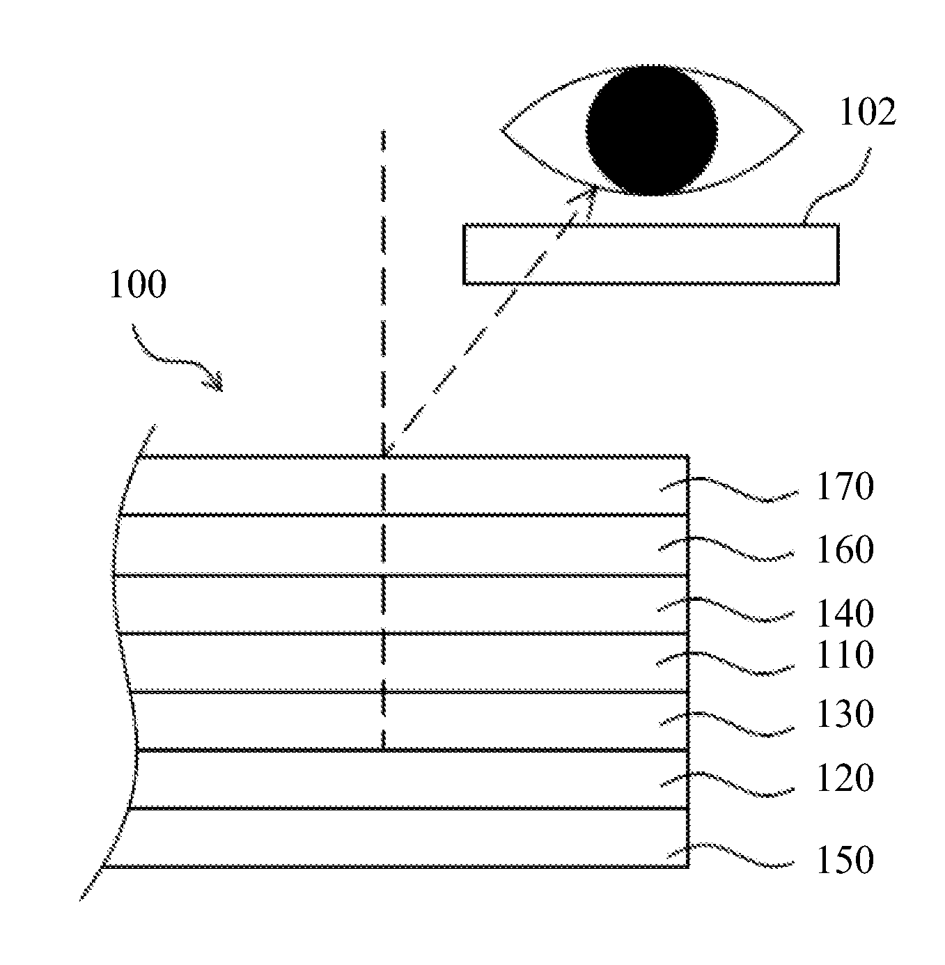
[0026]Referring to FIG. 1, a partially cross-sectional view showing a 3D display system according to an embodiment of the present invention is illustrated. The 3D display system of the present embodiment comprises a 3D display panel 100 and polarizer glasses 102. The 3D display panel 100 is capable of displaying 3D images. The 3D display panel 100 can be assembled with a backlight module (not shown), t...


PUM


Abstract

The present invention provides a 3D display panel and a 3D display system. The system comprises the 3D display panel and polarizer glasses. A first optical retardation value of a quarter wave (λ/4) retarder film of the 3D display panel can be designed according to a second optical retardation value of the polarizer glasses. The present invention can improve a narrow viewing angle problem existing in the conventional 3D display.

Description

FIELD OF THE INVENTION[0001]The present invention relates to a display panel and a display system, and more particularly to a three-dimensional (3D) display panel and a 3D display system for displaying 3D images.BACKGROUND OF THE INVENTION[0002]Liquid crystal displays (LCDs) have been widely applied in electrical products. Currently, most of LCDs are backlight type LCDs which include a liquid crystal panel and a backlight module.[0003]At present, the LCDs are capable of having a 3D image displaying function. For example, a 3D pattern retarder display, which has a half (½) wave plate and a quarter (¼) wave plate being disposed at an outer side of an LCD panel, is capable of displaying 3D images.[0004]In general, the pattern retarder display has left image pixels and right image pixels. The left image pixels are positioned at odd pixel rows (or even pixel rows) of the display, and the right image pixels are positioned at the other pixel rows thereof. When the light of the display pass...

Claims


Application Information

Patent Timeline
IPC IPC(8): G02F1/1335G02B30/25
CPCG02B27/2214H04N13/0409G02F2413/01G02B27/26G02F2001/133638G02F1/13363H04N13/31G02B30/25G02F1/133638G02B30/27
Inventor FANG, BINHSIAO, CHIA-CHIANGCHEN, CHIH-WEN
Owner SHENZHEN CHINA STAR OPTOELECTRONICS TECH CO LTD
Why Eureka
Try Eureka