Electrical machine with contact connectors

a technology of contact connectors and electrical machines, applied in the direction of windings, dynamo-electric components, supports/encloses/casings, etc., can solve the problems of reliability problems and relatively complex installation of electrical machines connected in this way, and achieve the effect of relatively easy disassembly

Inactive Publication Date: 2014-12-04
MICHELIN & CO CIE GEN DES ESTAB MICHELIN +1
View PDF3 Cites 2 Cited by
  • Summary
  • Abstract
  • Description
  • Claims
  • Application Information

AI Technical Summary

Benefits of technology

[0010]More specifically, the object of the present invention is to propose an electrical machine such that the disassembly is ...

Problems solved by technology

In such a particular configuration, one of the challenges of installation of an electrical machine lies in the connection of the machine to the external connections, in the present case an electrical harness of the vehicle.
It is thu...

Method used


Image

  • Electrical machine with contact connectors
  • Electrical machine with contact connectors
  • Electrical machine with contact connectors

Examples


Embodiment Construction

[0042]In the description of the figures, like elements in the figures will be denoted by the same reference.

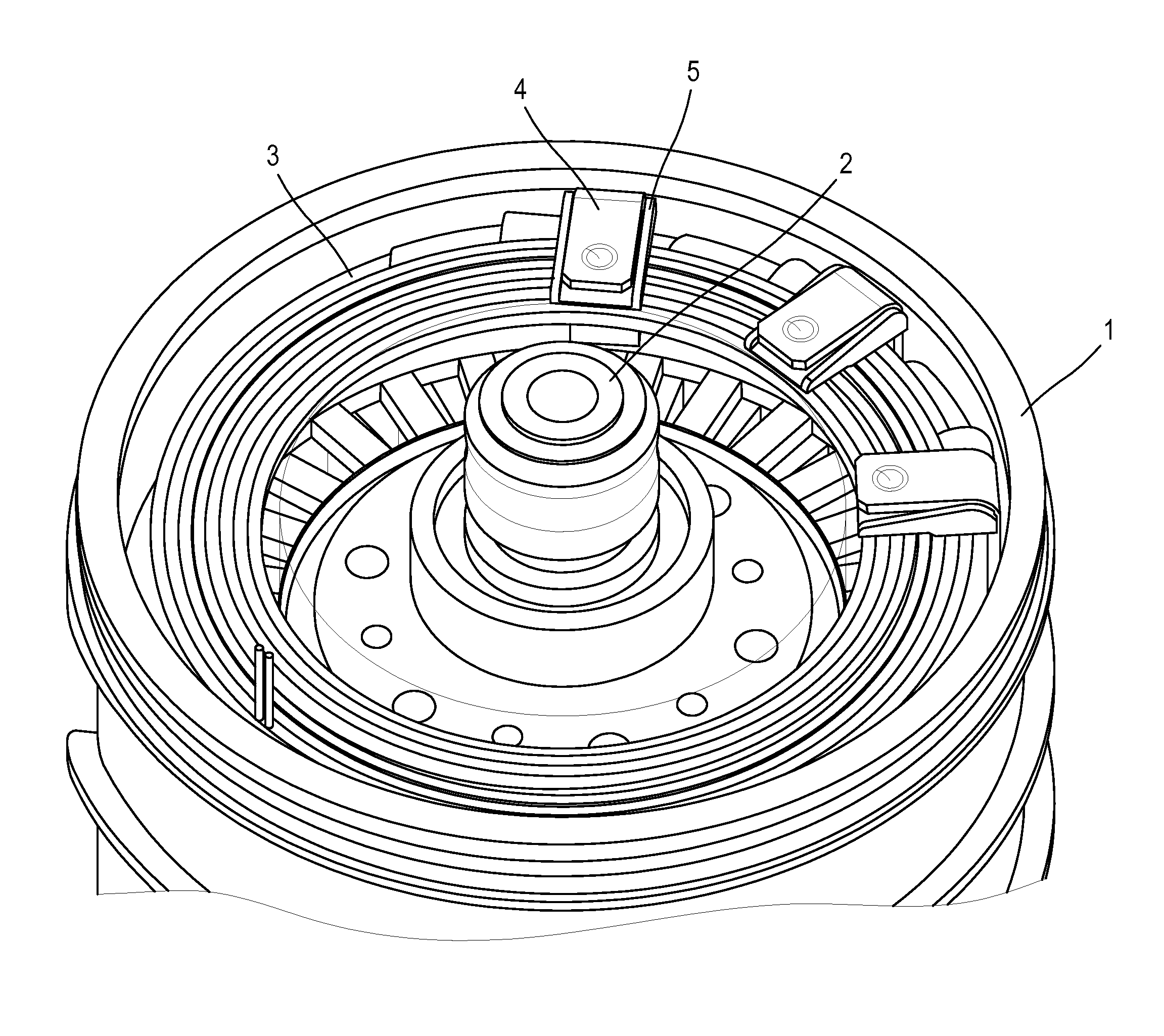
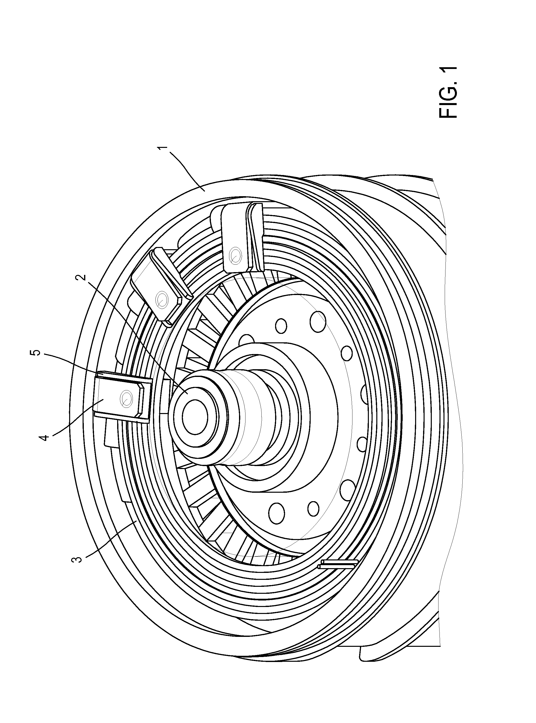
[0043]FIG. 1 shows a brushless electrical machine with permanent magnets. This machine is shown without its cover. The machine comprises a housing 1, in which a rotor 2 is installed in the axis of the housing, surrounded by a stator winding 3. This winding is three phase, that is to say the coils define three phases. In the example in FIG. 1, the machine comprises 3 identical connectors 4, each installed on an output of the winding. Furthermore, each connector is shaped around an insulating part 5.

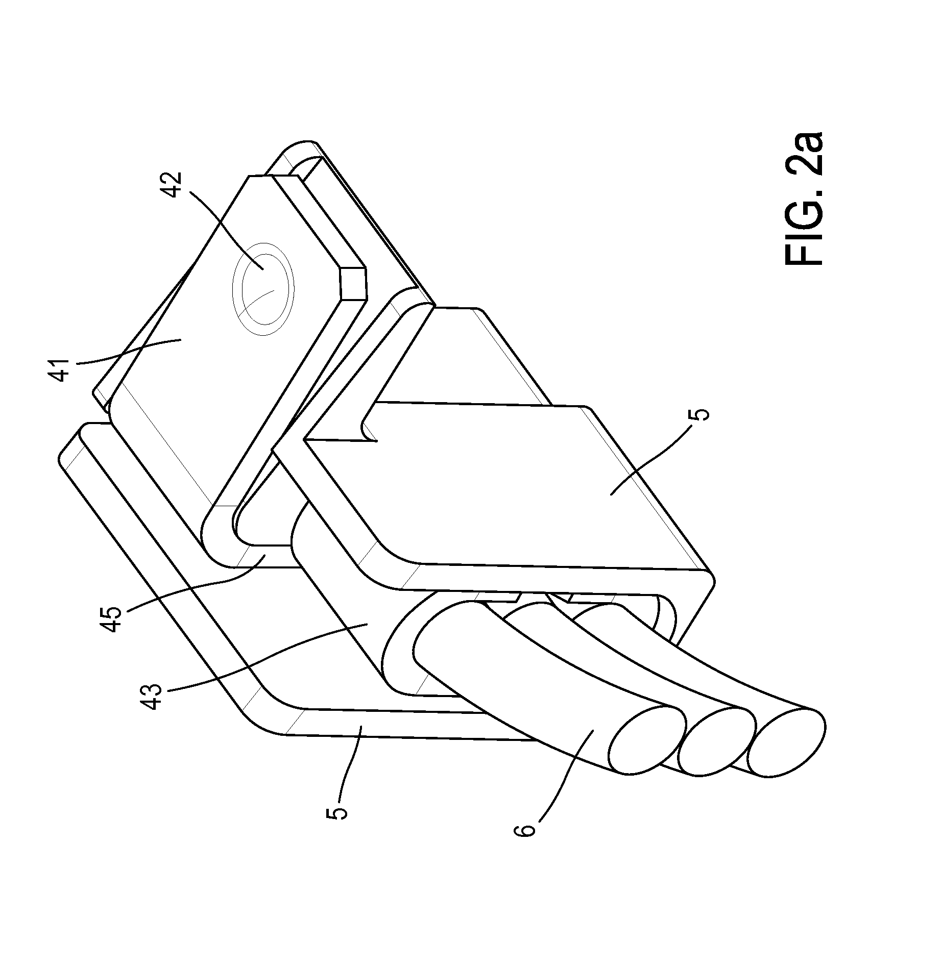
[0044]An electrical connector such as those shown in FIG. 1 is, initially, a non-folded conductive metal part, as shown in FIG. 6. During production of the electrical machine, a non-folded connector is fixed on a phase output of the stator winding. To this end, a fixing element 43 is crimped on a phase output, for example comprising three wires, so as to establish a connection.

[0045]...


PUM

PropertyMeasurementUnit
Angleaaaaaaaaaa
Phaseaaaaaaaaaa

Abstract

An electrical machine includes permanent magnets, a housing, a stator winding contained in the housing, and a cover. The cover includes at least two contactors and is connected to an electrical harness. The stator winding has at least two phase outputs, with at least one electrical connector being fixed to each phase output of the stator winding. Each of the electrical connectors has a contact surface intended to cooperate with a contact element. When the cover is installed on the housing, each contactor of the cover is in contact with a contact surface of a corresponding electrical connector fixed to a phase output of the stator winding, such that the electrical machine is connected to the electrical harness.

Description

FIELD OF THE INVENTION[0001]The present invention relates to electrical machines, in particular intended for installation in road vehicles.[0002]The present invention in particular relates to electrical machines with a stator winding. This invention can be applied, for example, with permanent magnets in brushless electrical machines.[0003]An electrical machine is a machine enabling the conversion between electrical energy and mechanical energy. This conversion can be implemented in both directions without the need for the machine to function as a generator or as a motor. There are different types of machines, that is to say D.C. machines or A.C. machines, which can be further sub-divided into synchronous or asynchronous machines. In order to perform this conversion, an electrical machine generally comprises a fixed part, referred to as a stator, and a rotatable part, referred to as a rotor.[0004]The electrical machines can be installed in all sorts of systems, in particular in a roa...

Claims


Application Information

Patent Timeline
IPC IPC(8): H02K5/22H02K15/12H02K15/00H02K15/04H01R4/18H02K11/00
CPCH02K5/225H01R4/18H02K11/0094H02K2203/06H02K15/0435H02K15/12H02K15/0068H02K3/50H02K15/0062Y10T29/49009
Inventor VEDY, BERTRAND
Owner MICHELIN & CO CIE GEN DES ESTAB MICHELIN
Why Eureka
Try Eureka