Microvalve Having Improved Resistance to Contamination

a micro-valves and resistance technology, applied in the field of micro-valves, can solve the problems of inability to move freely between the displaceable member and the displaceable member, and inability to remove the displaceable member

Inactive Publication Date: 2014-12-25
ZHEJIANG DUNAN HETIAN METAL CO LTD
View PDF34 Cites 11 Cited by
  • Summary
  • Abstract
  • Description
  • Claims
  • Application Information

AI Technical Summary

Benefits of technology

[0007]This invention relates to an improved structure for a microvalve that resists interference with the free movement of a displaceable member of the microvalve that might otherwise result from the presence of particulate contaminants contained in the fluid flowing therethrough. The microvalve includes a base plate including a surface, a recessed area provided within the surface, a first fluid port provided within the recessed area, and a first sealing structure extending about the first fluid port. The microvalve also includes a cover plate including a surface, a recessed area provided within the surface, a second fluid port provided within the recessed area, and a second sealing structure extending about the second fluid port. An intermediate plate has a first surface that abuts the surface of the base plate and a second surface that abuts the surface of the cover plate. The intermediate plate includes a displaceable member that is movable between a closed position, wherein the displaceable member cooperates with the first and second sealing structures to prevent fluid communication between the first and second fluid ports, and an opened position, wherein the displaceable member does not cooperate with at least a portion of at least one of the first and second sealing structures to prevent fluid communication between the first and second fluid ports.

Problems solved by technology

However, it has been found that when this conventional microvalve structure is used to control the flow of fluid containing solid particles (such as particulate contaminants that may be contained within the fluid), such particles may become jammed between the displaceable member and the adjacent portions of the microvalve that define the closed internal cavity.
The jamming of such particles can, in some instances, undesirably interfere with the free movement of the displaceable member between the closed and opened positions.

Method used


Image

  • Microvalve Having Improved Resistance to Contamination
  • Microvalve Having Improved Resistance to Contamination
  • Microvalve Having Improved Resistance to Contamination

Examples


Embodiment Construction

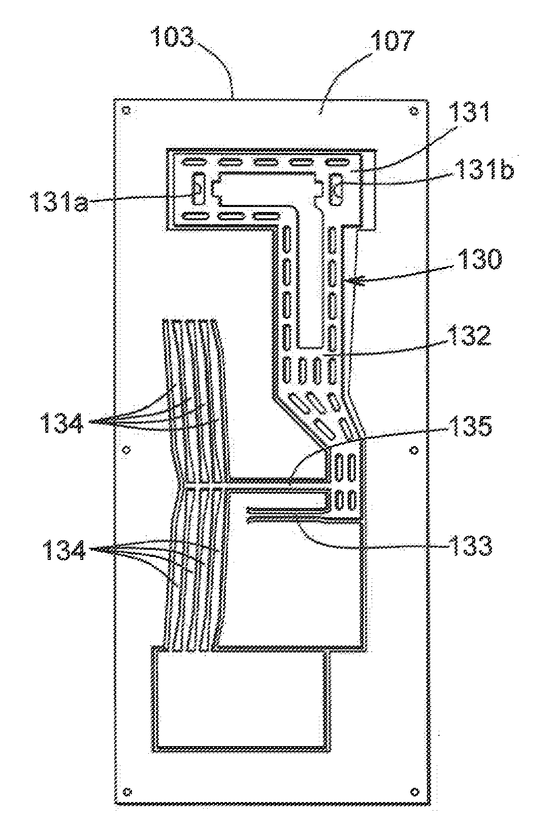
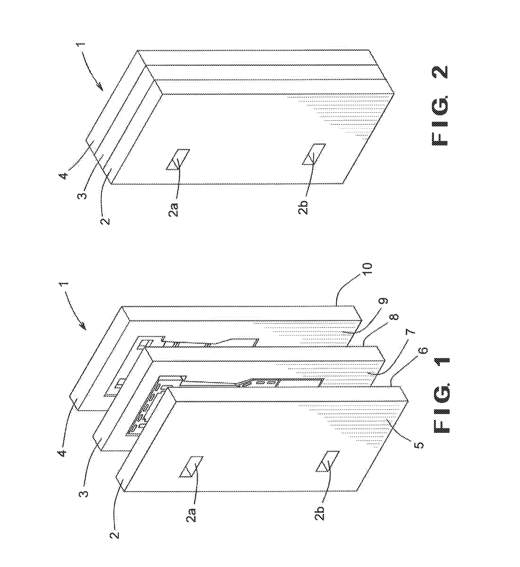
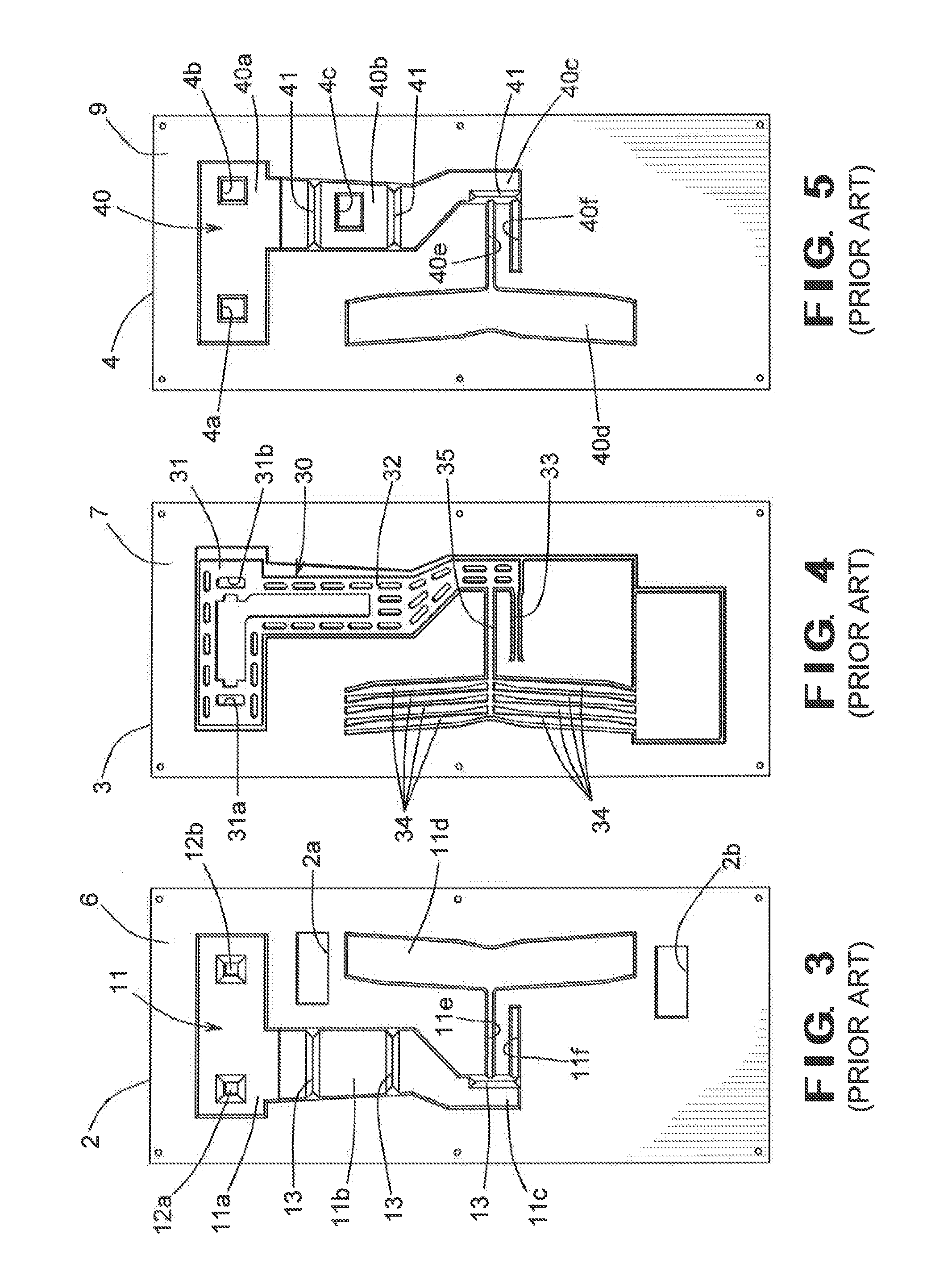
[0033]Referring now to the drawings, there is illustrated in FIGS. 1 and 2 a basic structure of a microvalve 1 that, to the extent shown, is representative of both a conventional structure for a microvalve and an improved structure for a microvalve in accordance with this invention. The illustrated microvalve 1 includes a cover plate 2, an intermediate plate 3, and a base plate 4. The cover plate 2 has an outer surface 5 and an inner surface 6. The cover plate 2 also has one or more openings (two of such openings 2a and 2b are shown in the illustrated embodiment) formed therethrough that, in a manner that is well known in the art, allow one or more electrically conductive wires (not shown) to pass therethrough. The intermediate plate 3 has a first surface 7 and a second surface 8. The base plate 4 has an inner surface 9 and an outer surface 10. The base plate 4 also has a one or more openings (three of such openings 4a, 4b, and 4c are shown in the illustrated embodiment) formed ther...


PUM


Abstract

A microvalve includes a base plate including a surface, a recessed area provided within the surface, a first fluid port provided within the recessed area, and a first sealing structure extending about the first fluid port. The microvalve also includes a cover plate including a surface, a recessed area provided within the surface, a second fluid port provided within the recessed area, and a second sealing structure extending about the second fluid port. An intermediate plate is disposed between the base plate and the cover plate and includes a displaceable member that is movable between a closed position, wherein the displaceable member cooperates with the sealing structures to prevent fluid communication between the fluid ports, and an opened position, wherein the displaceable member does not cooperate with at least a portion of the sealing structures to prevent fluid communication between the fluid ports.

Description

CROSS-REFERENCE TO RELATED APPLICATIONS[0001]This application claims the benefit of U.S. Provisional Application No. 61 / 838,529, filed Jun. 24, 2013, the disclosure of which is incorporated herein by reference.BACKGROUND OF THE INVENTION[0002]This invention relates in general to microvalves for controlling the flow of fluid through a fluid circuit. In particular, this invention relates to an improved structure for such a microvalve that resists interference with the free movement of a displaceable member of the microvalve that might otherwise result from the presence of particulate contaminants contained in the fluid flowing therethrough.[0003]Generally speaking, a micro-electro-mechanical system is a system that not only includes both electrical and mechanical components, but is additionally physically small, typically including features having sizes in the range of ten micrometers or smaller. The term “micro-machining” is commonly understood to relate to the production of three-di...

Claims


Application Information

Patent Timeline
Patent Type & Authority Applications(United States)
IPC IPC(8): F16K99/00
CPCF16K99/0044F16K2099/0073
Inventor FULLER, EDWARD NELSONARUNASALAM, PARTHIBANYANG, CHENLUCKEVICH, MARKOJEDA, JOE
Owner ZHEJIANG DUNAN HETIAN METAL CO LTD
Why Eureka
Try Eureka