Vented dome

a venting dome and dome technology, applied in the field of hearing devices, can solve the problems of fess likely blockage of the vent pathway, and achieve the effects of reducing the size of the venting pathway, reducing the sound transmission, and reducing the venting

Active Publication Date: 2015-01-01
OTICON
View PDF7 Cites 10 Cited by
  • Summary
  • Abstract
  • Description
  • Claims
  • Application Information

AI Technical Summary

Benefits of technology

[0025]In another embodiment at least part of the material of the flexible mounting insert and/or a part of the material at the proximity of the distal end of the thin acoustic tube comprise piezoelectric properties. Applying a current to the material parts with piezoelectric properties can lead to a volume increase of the material, which for example decreases the size of the venting pathway. The piezoelectric materials can also be used to rotate the consecutively arranged filter elements, e, g, gratings, sieves or similar filters, to each other, leading to a misalignment of the filters, which can lead to a decreased sound transmission or decreased venting effect, as smaller transmission area is available for sound to be transmitted from the ear canal to the outside of the ear.
[0026]Preferably the processing unit is connected to the sensors that monitor the acoustic environment. The processing unit can generate control signals in dependence of the difference between the parameters of the acoustic environments on the distal and

Problems solved by technology

Further the vent pathway is fess likely to be blocked th

Method used


Image

  • Vented dome
  • Vented dome
  • Vented dome

Examples


first embodiment

[0048]FIG. 3 presents a flexible mounting insert 34 with a filter bridge 54 in front of the core hole 42 intended as a wax filter. The filter bridge 54 of this embodiment contains a small filter bridge hole 56 and is affixed to the dome shaped part 40 of the flexible mounting insert 34 with a filter bridge affixture 58. Sound can pass either through the filter bridge hole 56 or through an indirect pathway along the sides of the filter bridge 54 into the core hole 42. Ear wax is stopped by the filter bridge 54, as the ear wax is too large to pass neither the filter bridge hole 56 nor the indirect pathway along the sides of the filter bridge 54 into the core hole 42.

[0049]FIG. 4 is a longitudinal cut through the first embodiment of the flexible mounting insert 34, Behind the filter bridge 54 is an entrance area 60 of the core hole 42 which is enclosed and formed by the dome shaped part 40 of the mounting insert 34. The entrance area 60 may contain additional filter elements (not shown...

second embodiment

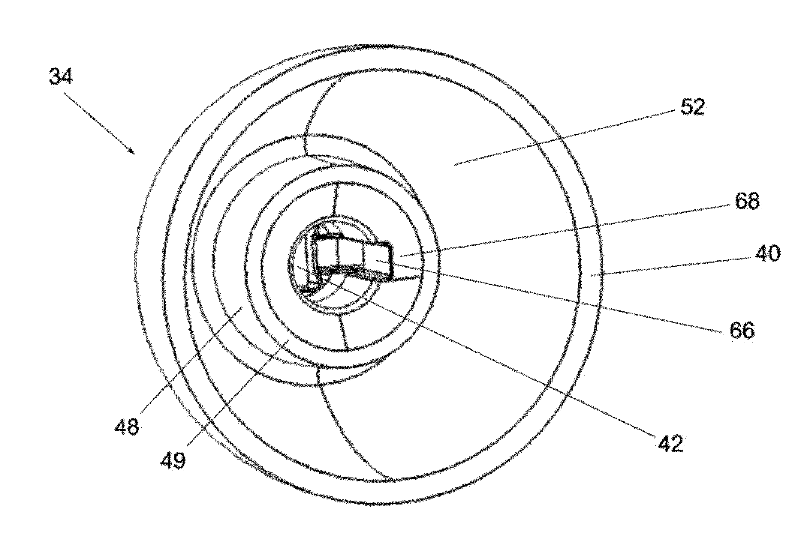
[0050]FIG. 5 shows the flexible mounting insert 34 which contains only one vent groove 66 in a box-like form along the circumference of the core hole 42 extending to the outlet 68 which ends with the proximal end 49 of the core pathway projection.

[0051]FIG. 6 presents a third embodiment of the flexible mounting insert 34 which is almost identical to the second embodiment, but contains four smaller sized box-like vent grooves 66 which are arranged symmetrically around the core hole 42. The vent grooves 66 extend to the outlet 68, which ends at the proximal end 49 of the core pathway projection 48.

[0052]In FIG. 7 an acoustic tube 22 with a distal end 28 with a ball joint 70 having a spherical shape is connected to the mounting insert 34. The mounting insert 34 is comprised of two parts, an inner core part 72 which is of a hard material and an outer part 74 which is of a softer and flexible material. The inner core part 72 adjoins to the ball joint 70 which encloses the core pathway 46...

fourth embodiment

[0054]FIG. 8 presents the flexible mounting insert 34 which contains a removable wax filter element 76. The wax filter element 76 is located behind the core hole 42 in the core pathway 46 and enclosed by the core pathway projection 48. A wax filter grating 82 has holes 84 that allow passage of sound, while the grating 82 prevents ear wax to enter the core pathway 46 of the mounting insert 34. The wax niter element 76 contains a vent groove 66, which is intended for venting. The vent groove 66 is therefore located behind the wax filter grating 82, which means that the wax filter element 76 protects the core pathway 46 for sound transmission and the vent pathway of the vent groove 66 from becoming blocked by ear wax. Preferably the wax filter grating 82 contains a coating on its distal side oriented into the ear canal, which dampens sound. Also a coating which interacts with ear wax to liquefy the ear wax can be applied on the wax filter element 76.

[0055]FIG. 9 shows a fifth embodimen...


PUM


Abstract

A hearing device includes a BTE unit and a thin acoustic tube. The BTE unit includes a microphone, an amplifier, a power source, and a receiver and is configured to mount behind or on a user's ear. The tube includes a proximal end and a distal end with the proximal end and the distal end being connected to the receiver and to a flexible mounting insert respectively. The insert comprises a dome shape part and at least one core hole permeable for sound transmitted from the tube, which is configured to arrange in a user's ear canal to transmit sound generated by the BTE unit to a tympanic membrane of the user. The inserts diameter is adapted to at least have the same diameter as user's ear canal diameter to dose the ear canal of the user and has at least one internal vent pathway located on the circumference of the core hole.

Description

FIELD OF THE INVENTION[0001]The present invention concerns a hearing device comprising a BTE (Behind-The-Ear) unit, which is adapted to be mounted behind or on the ear of a user and further comprising a thin acoustic tube connected to a flexible mounting insert, which comprises a dome shape part and at least one hole for venting.DESCRIPTION OF RELATED ART[0002]Hearing devices are generally characterized by the way they are fitted to the ear of a user. The BTE type hearing device is mounted behind or on the ear of a user and comprises a BTE unit and a thin tube, where the BTE unit comprises a microphone, an amplifier, a power source and a receiver (speaker). The BTE unit is connected to the thin tube with a distal end of the tube fitted in the ear canal of a user, which transmits sound from the BTE unit or a speaker unit (receiver unit) at the end of the thin tube to the tympanic membrane in the ear canal of the user. A description on various other types of hearing devices can for ex...

Claims


Application Information

Patent Timeline
IPC IPC(8): H04R25/00
CPCH04R25/652H04R25/654H04R2460/11H04R2225/021H04R2460/05H04R2225/63H04R2225/0213H04R2225/0216
Inventor MOLLER, KENNETH RUESKOVWALTHER, PATRICKJIANG, NAN
Owner OTICON
Why Eureka
Try Eureka