Handle structure for a draw bar of a luggage case

a technology of draw bar and handle, which is applied in the direction of traveling carriers, travelling articles, other accessories, etc., can solve the problem of inconvenient use of luggage cases

Inactive Publication Date: 2015-09-17
LAI
View PDF0 Cites 1 Cited by
  • Summary
  • Abstract
  • Description
  • Claims
  • Application Information

AI Technical Summary

Benefits of technology

[0009]The primary objective of the present invention is to provide a handle structure for a draw bar of a luggage case, wherein the possibility that the draw bar will automatically pop out of the luggage case when the press portion is accidentally pressed can be prevented.
[0011]The handle structure for the draw bar of the luggage case in accordance with the present invention offers the following advantages: 1. the handle casing protects the handle of the draw bar from unexpectedly popping out of the luggage case. 2. The handle is able to pivot with respect to the luggage case, allowing the user to tow at a comfortable angle. 3. The present invention is provided with two control members, therefore, any user who is left or right handed can easily handle one of the control members with one hand.

Problems solved by technology

However, the draw bar would be projected out of the luggage case when the press button is touched by accident, which is likely to cause rupture.
However, this also makes the luggage case inconvenient to use, since it has to push the protection cover back and forth between the covered and uncover positions, every time the draw bar needs to be pulled out or pushed into the luggage case.

Method used


Image

  • Handle structure for a draw bar of a luggage case
  • Handle structure for a draw bar of a luggage case
  • Handle structure for a draw bar of a luggage case

Examples


Embodiment Construction

[0020]The present invention will be clearer from the following description when viewed together with the accompanying drawings, which show, for purpose of illustrations only, the preferred embodiment in accordance with the present invention.

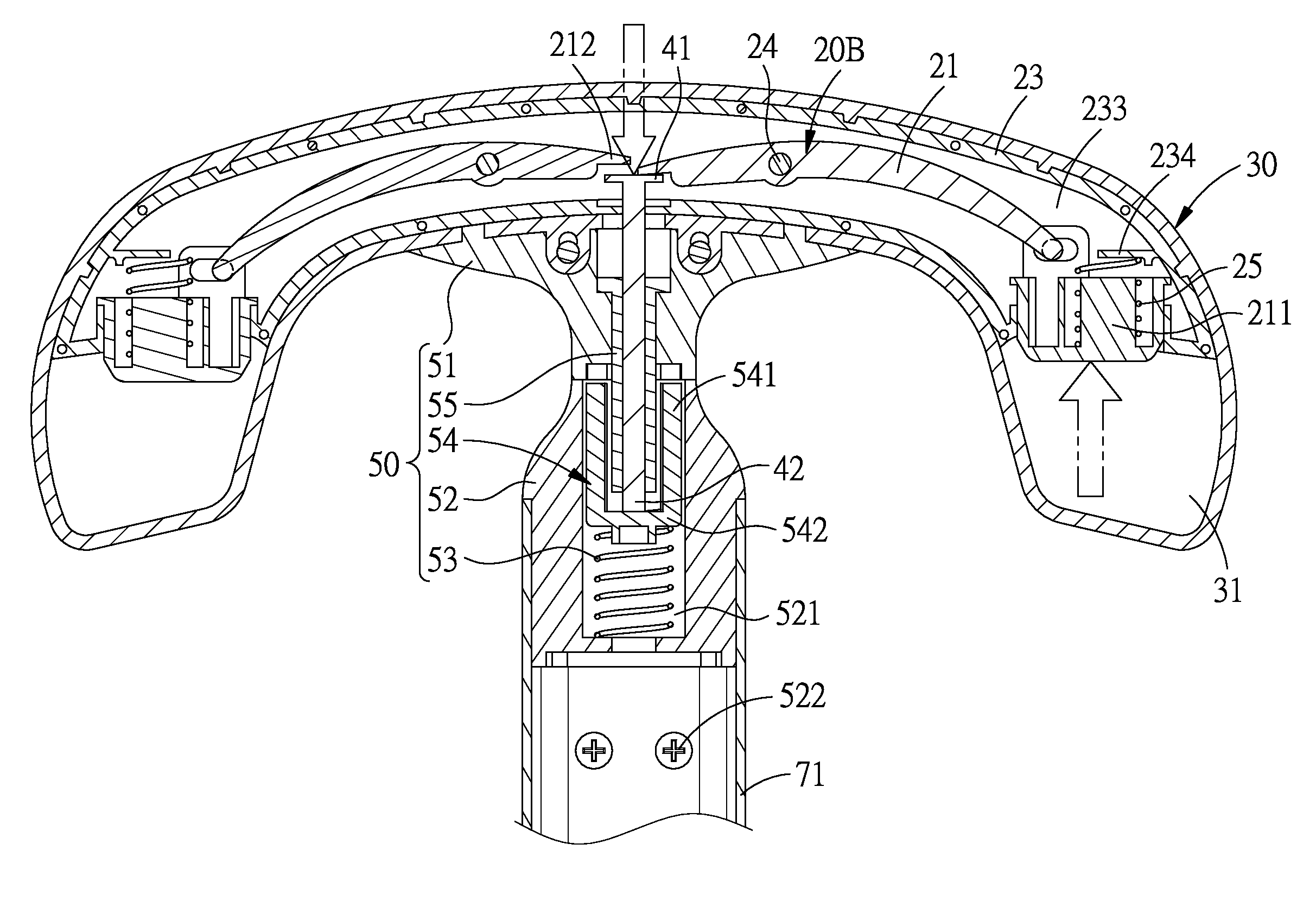
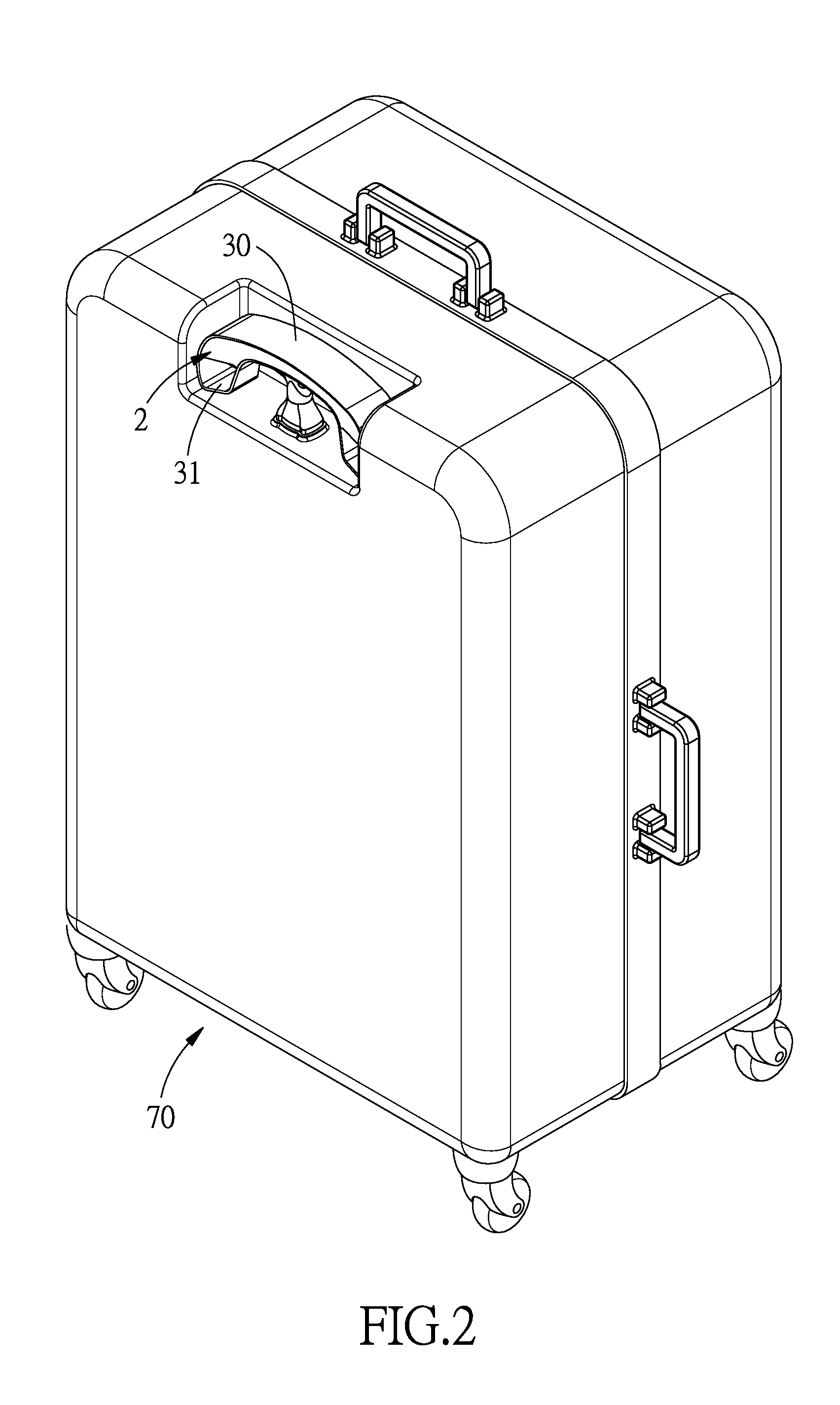
[0021]Referring to FIGS. 2-4, a handle structure for a draw bar of a luggage case 70 in accordance with a preferred embodiment of the present invention is shown, and the draw bar comprises a rod portion 71 which is capable of sliding in and out of the luggage case 70. The handle structure comprises: a handle 2, a handle casing 30, a push member 40, and a connecting device 50.

[0022]The handle 2 includes two control members 20A and 20B, each of which includes a movable member 21 which is pivoted to a stationary member 23 via a pivot point 22. In this embodiment, the stationary member 23 includes a first cover member 231 and a second cover member 232 which are assembled together to define an inner space 233. Each of the movable members 21 is pivoted...


PUM


Abstract

A handle structure for a draw bar of a luggage case includes a handle, a handle casing, a push member, and a connecting device. The handle includes two control members each having a movable member pivoted to a stationary member. The movable member includes a press portion and a reaction portion at two sides of the pivot point. The handle casing is fixed around the handle to hold the press portion. The push member has a head portion disposed in the handle casing and connected to the reaction portions, and a shaft portion extending out of the handle casing. The connecting device is fixed to the rod portion, and the shaft portion is inserted in the connecting device. When the press portion is subjected to a force in a direction, the reaction portion is moved toward that direction, the reaction portion moves the shaft portion toward the rod portion.

Description

BACKGROUND OF THE INVENTION[0001]1. Field of the Invention[0002]The present invention relates to a draw bar of a luggage case, and more particularly to a handle structure for a draw bar of a luggage case.[0003]2. Description of the Prior Art[0004]Luggage cases are mostly provided with a draw bar to be pulled by a user, and the draw bar is usually retractile. As shown in FIG. 1, a conventional luggage case 10 comprises a draw bar 11. The draw bar 11 includes a rod portion 12 which and a handle 13 disposed at the end of the rod portion 12. On the handle 13 is provided a press button 14.[0005]The luggage case needs to be put away when not in use, so the rod portion 12 of the draw bar 11 can be pushed into the luggage case 10 and locked therein, which not only saves storage space, but also prevent rupture of the draw bar 11 caused by unexpected collision. The draw bar 11 can also be automatically extended out of the luggage case 10 by pressing the press button 14, so that the user can t...

Claims


Application Information

Patent Timeline
Patent Type & Authority Applications(United States)
IPC IPC(8): A45C13/26B25G1/04
CPCB25G1/04A45C13/262A45C2013/265
Inventor LAI
Owner LAI
Why Eureka
Try Eureka