Noise Making Device

a noise-making device and noise-generating technology, applied in the direction of toys, rattles, packaging, etc., can solve the problems of large or cumbersome carrying, and the self-limiting of vocal expressions of limited duration and volum

Inactive Publication Date: 2016-04-14
CARROLL GEOFFREY PORTER
View PDF4 Cites 1 Cited by
  • Summary
  • Abstract
  • Description
  • Claims
  • Application Information

AI Technical Summary

Benefits of technology

[0005]According to another embodiment, an apparatus is provided for use with a hand-held tube structure, of the type used to contain and dispense liquid (e.g., a bottle) with a wall having a length extending a first distance along a first axis, between first and second opposing ends. The wall has a variable width along a second axis transverse to the first axis. The length of the structure is elongate with respect to a maximum width. When the tube structure occupies an erect orientation: the first end is directly over the second end, and a first portion of the wall defines a relatively narrow, low volume neck region positioned above a second portion of the wall. This defines a relatively wide, higher volume container region relative to the neck region. The neck region includes an opening for dispensing liquid from the container region. The apparatus includes at least a first rod member having first and second opposing ends; a first mass attached to the first end of the rod member; and a support member pivotally attached to the second end of the rod member. The support member is sized and shaped for attachment about the tube opening so that, when the first rod member end and the mass are positioned within the container region of the tube structure, the support member is positioned in or about the opening, and the rod member and the mass are pivotally positioned and supported by the support member so that the mass can be swung (i) from the support member within the container region and (ii) through the first axis to strike opposing parts of the wall. The rod member is of sufficient stiffness that, when the first mass swings from the rod, the rod stiffness prevents the first mass from travelling from the container region into the neck region.

Problems solved by technology

However, persons desiring to generate such expressions often find themselves limited to generating vocal expressions of limited duration and volume.
While various devices are available to otherwise generate expressive sounds, these are often large or cumbersome to carry and are normally not available for purchase at the venue.

Method used


Image

  • Noise Making Device
  • Noise Making Device
  • Noise Making Device

Examples


third embodiment

[0071]FIGS. 3A through 3D illustrate features of a noise-making assembly 14a according to the invention. In lieu of providing the cap 40, two masses 60, each attached to a rod member 64, are suspended from a cap in the form of a stopper 90. As shown in the figures, the two illustrated rod members are of different lengths so that one rod member extends closer to the second end than does the other rod member. Also as shown in the figures, the exemplary stopper may have a slightly tapered profile in which an upper stopper surface 92 has a greater outside dimension than a lower stopper surface 94. When the stopper 90 is installed in a bottle opening 22 the upper stopper surface 92 is positioned along the first bottle end 26 near the opening 22 (e.g., outside the opening), while the lower stopper surface 94 is positioned within the bottle interior along or adjacent the neck region 18 and near the opening 22.

[0072]The stopper 90 may comprise a size-adjustable rubber-like mass or a cork bo...

fourth embodiment

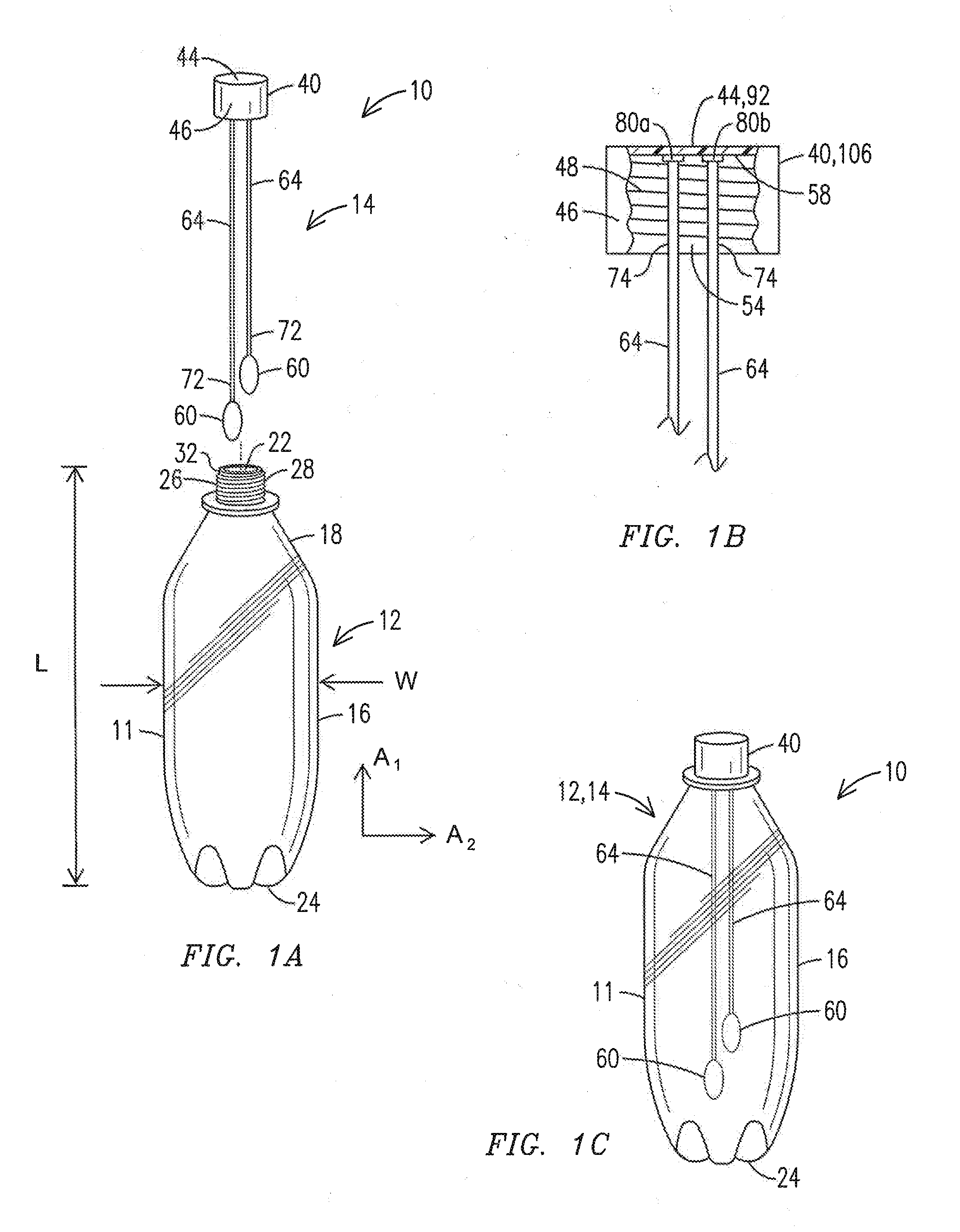
[0073]In addition to providing masses 60 and rod members 64 suspended from a cap 40 or a stopper 90, a noise-making assembly 14b according to the invention includes a handle 104. The handle 104 may extend from the upper surface 44 / 92 of a cap or a stopper and may be integrally formed with the cap or stopper, e.g., in a molding process. FIGS. 4A and 4B illustrate one example of the assembly 14b comprising a cap 106, having features like the cap 40. With reference to FIG. 1B, the cap 106 includes the cylindrically shaped wall 46 and an interior surface 58 of the circular shaped cap top 44 which adjoins the interior wall surface 54. The cap 106 also includes mating threads 48 formed along the interior surface 54 of the cap wall 46. With this arrangement the cap 40 may be screwed on to the first end 26 of the bottle 12 in like manner to that described for the cap 40 with reference to FIG. 1.

embodiment 10

[0074]Like the embodiment 10, the rod members 64 of the noise-making assembly 14b are attached to and extend away from fixation points 80a, 80b to suspend the masses 60 from the cap 106. The handle 104 extends in a direction away from the rod members 64 and masses 60. In one implementation, the handle 104 may be integrally formed with the cylindrically shaped wall of the cap 106, e.g., as an extension of the cap wall 46. When the handle 104 and cap 40 are integrally formed, e.g., in a molding process, the portion corresponding to the cap wall 46 shown in FIG. 1 is a portion of a larger wall 108 which provides the handle 104 as well.

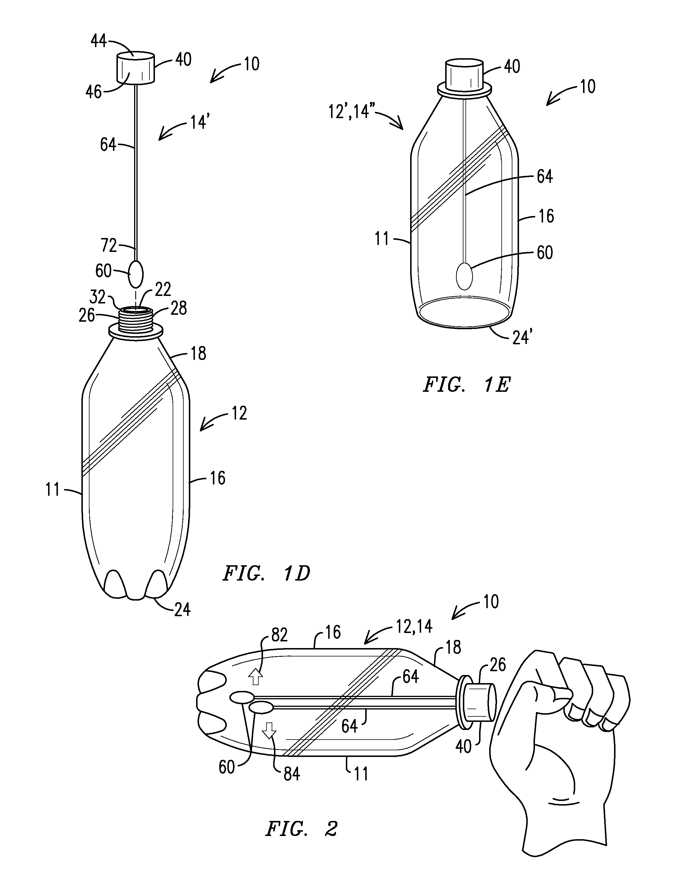
[0075]With the handle 104 extending away from the bottle opening 22, the hand position shown in FIG. 2 for holding a bottle 12 containing a noise-making assembly may also be applied to the handle 104. Instead of applying the hand to the first bottle end 26 or the narrowing neck region 18 of the bottle, the hand may grasp the handle 104 to impart motion to...


PUM


Abstract

In one embodiment, an apparatus for use with a tube structure (e.g., a bottle) includes a wall which extends between first and second ends. A first rod member has first and second ends with a mass attached to the first end and a support member pivotally attached to the second end for attachment about a tube opening. When the first rod member end and the mass are positioned within the tube, the support member is positioned in or about the opening, and the rod member and the mass are pivotally positioned and supported by the support member. The mass can be swung from the support member within the tube structure to strike opposing first and second parts of the wall.

Description

PRIORITY BASED ON RELATED APPLICATION[0001]This application claims priority to U.S. Provisional Patent Application 62 / 061,314, filed 8 Oct. 2014. This application is a continuation in part of U.S. application Ser. No. 14 / 018,565 filed Sep. 5, 2013.FIELD OF THE INVENTION[0002]The present invention relates to noise making devices of the type used for attendees of events and celebrations and, more particularly, to an apparatus manually operable in conjunction with a container or other tubular structure to generate sound.BACKGROUND OF THE INVENTION[0003]During competitive games and other types of events held in large venues, groups of people often make efforts to generate loud expressions of enthusiasm or to cheer for a sports team, or to audibly affirm a person or a cause. However, persons desiring to generate such expressions often find themselves limited to generating vocal expressions of limited duration and volume. While various devices are available to otherwise generate expressiv...

Claims


Application Information

Patent Timeline
Patent Type & Authority Applications(United States)
IPC IPC(8): A63H5/00
CPCA63H5/00A63H37/00B65D81/36G10K1/071G10K3/00
Inventor CARROLL, GEOFFREY PORTER
Owner CARROLL GEOFFREY PORTER
Why Eureka
Try Eureka