Ceiling fan kit and electrical connector with mounting method

a technology of ceiling fans and mounting methods, which is applied in the direction of positive displacement liquid engines, piston pumps, coupling device connections, etc., can solve the problems of time-consuming, cumbersome, laborious ceiling fan installation, etc., and achieves the effect of reducing labor intensity, time-consuming and cumbersome connections

Active Publication Date: 2016-04-21
HUNTER FAN
View PDF7 Cites 36 Cited by
  • Summary
  • Abstract
  • Description
  • Claims
  • Application Information

AI Technical Summary

Problems solved by technology

Traditionally, ceiling fan installation is laborious, time consuming and often a cumbersome practice.
Connecting the electrical wires is a time consuming and cumbersome practice, involving: (1) threading electrical wires through the various parts of the ceiling fan assembly, often including a downrod; (2) cutting and stripping the fan wires per manufacturer's instruction; (3) joining the structure electrical wires to the fan electrical wires by using wire connectors, such as wire nuts, per manufacturer's instructions, which may include both single and dual wall switch wiring instructions; (4) securing the wire connectors with electrical tape; and (5) tucking wires into the electrical box ensuring the live wires and ground wires are on opposite sides of the electrical box.
Cutting, stripping, and joining the wires during fan installation is often the most cumbersome task of the process.
However, if the ceiling fan mounts to a relatively short ceiling, the installer must cut the fan electrical wires to an appropriate length.

Method used


Image

  • Ceiling fan kit and electrical connector with mounting method
  • Ceiling fan kit and electrical connector with mounting method
  • Ceiling fan kit and electrical connector with mounting method

Examples


Embodiment Construction

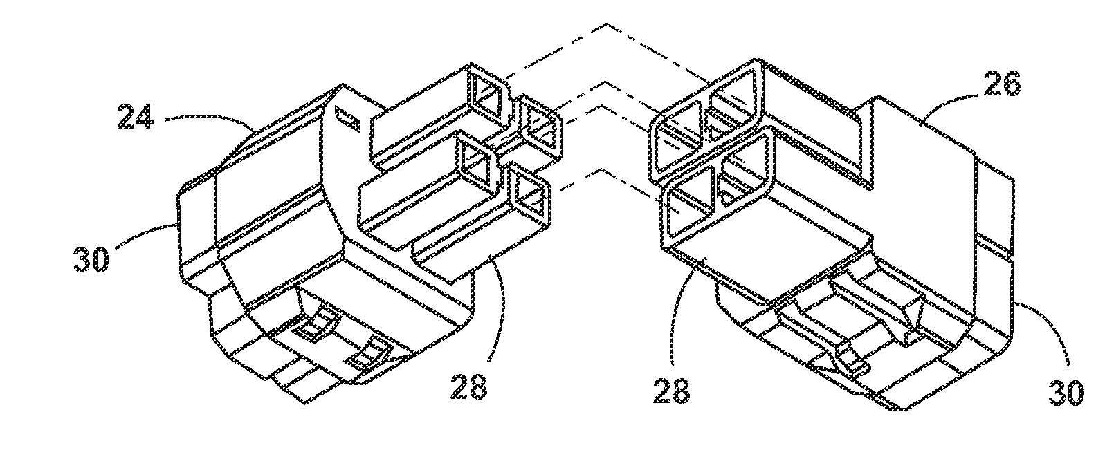
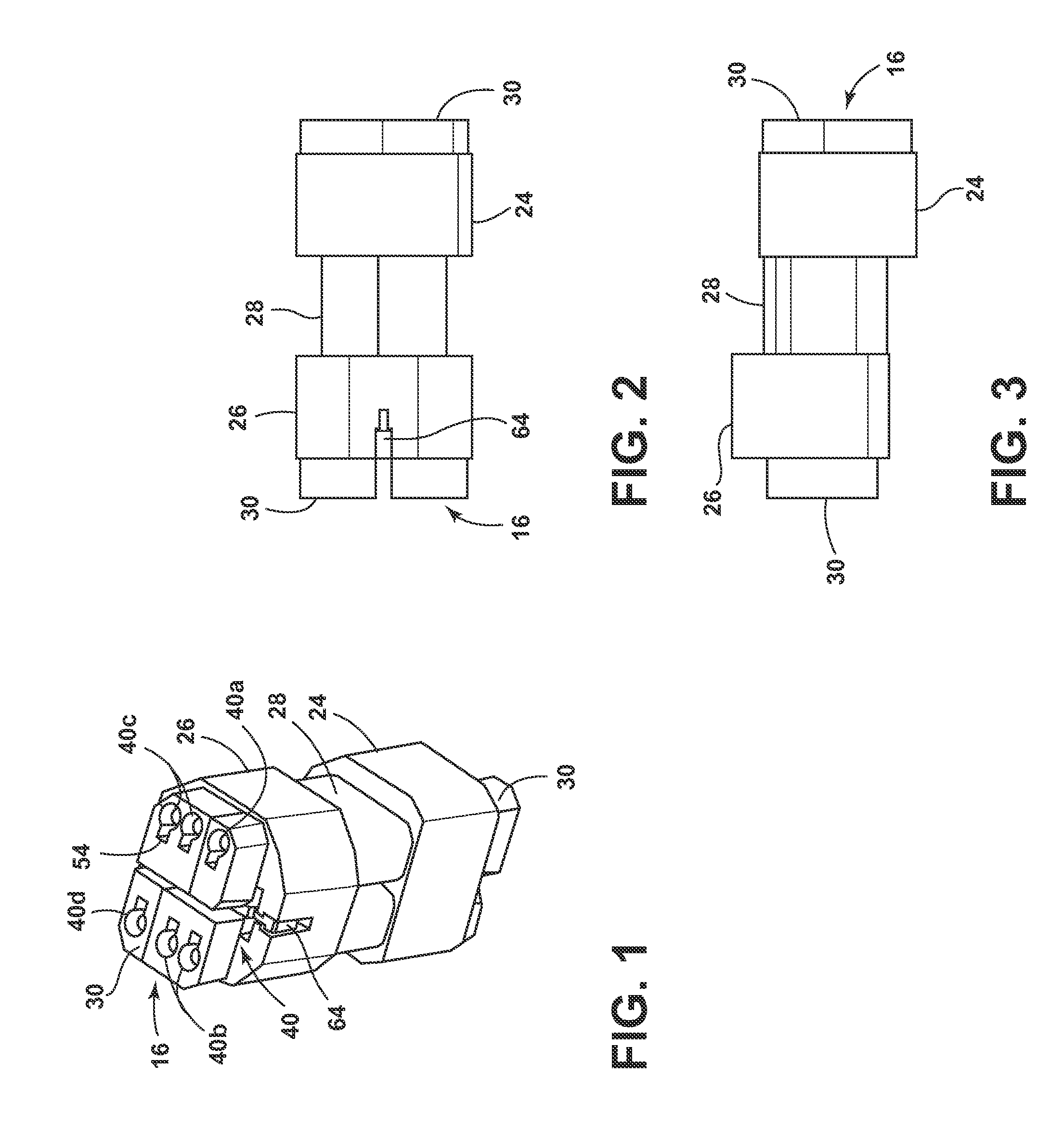
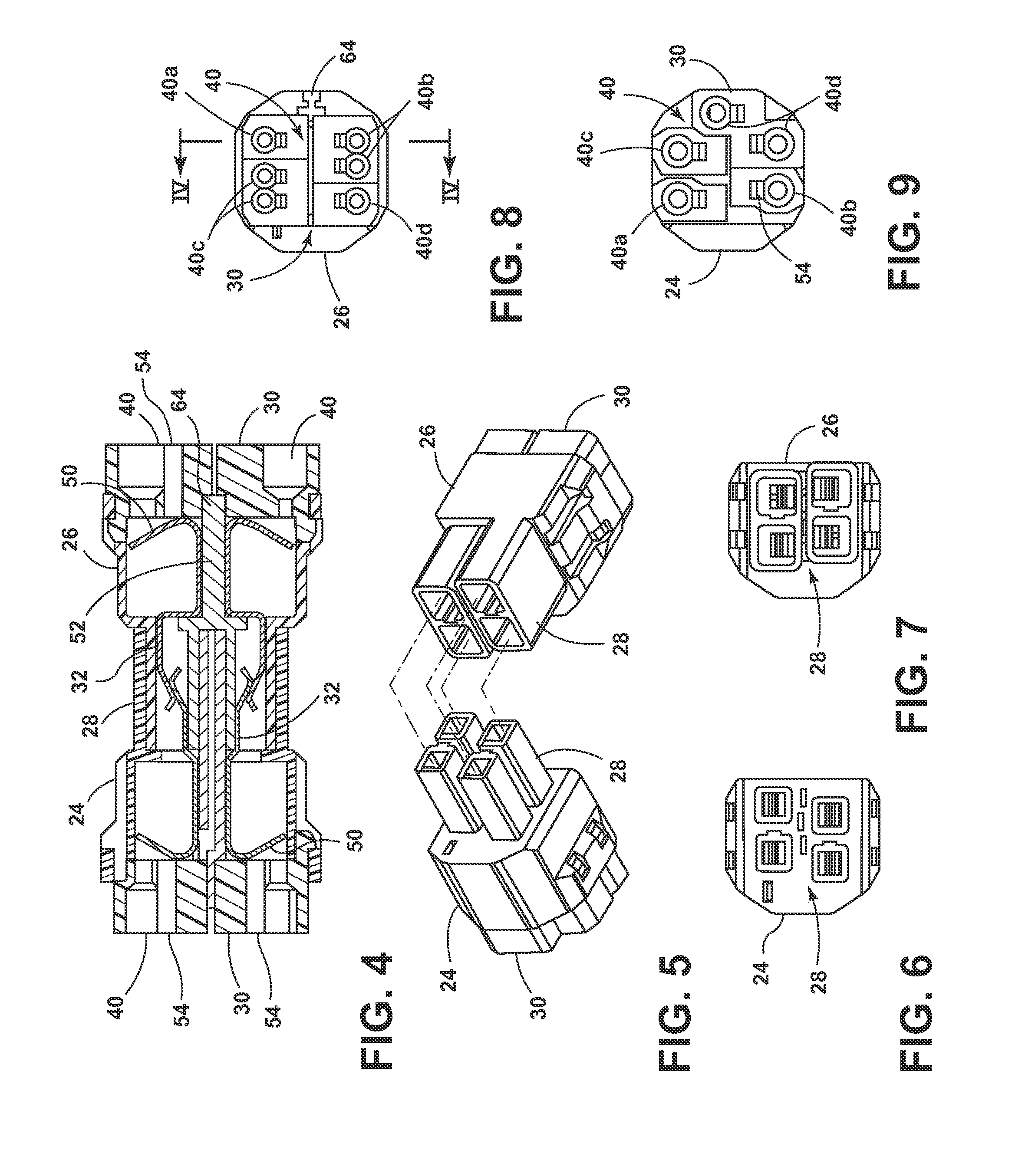
[0077]Referring generally to FIGS. 1-20, and more specifically to FIGS. 18-20, a ceiling fan 10 adapted to be coupled to a ceiling or other structure 12 having electrical wiring leads 14a 14e by way of a push-in connector 16 is disclosed. The ceiling fan 10 comprises a fan motor assembly 18 with an electric motor (not shown) having electrical fan wiring leads 20a-20d, threadable through a downrod 21 or pre-threaded through a pre-wired downrod 22, and / or canopy assembly (not shown) adapted to be mounted to the ceiling 12, wherein the electrical fan wiring leads 20a-20d are releasably connected to the push-in connector 16. Referring generally to FIGS. 1-20, the push-in connector 16 separates into a plug portion 24 and socket portion 26 (FIG. 5), each having a proximal end 28 and a distal 30 end, with the proximal direction defined at the one closer to each other. The plug portion 24 and socket portion 26 releasably connect at the proximal ends 28 to form a plug and socket combination ...


PUM


Abstract

A plurality ceiling fan kits comprising one or more pre-wired downrods or a set of pre-wired downrods having internal wiring terminating on one or more ends in wire leads made of electrically conductive materials. Different electrical connectors, for use with the ceiling fan kits and pre-wired downrods, are adapted to electrically couple one or more sets of wiring by pushing in the electrically conductive wire leads into a plurality of ports disposed on the electrical connectors. The electrical connectors may include a jumper for switching between a single- and dual-power supply switch configuration and indicia for identifying the insertion of a wire into a corresponding port. A method of mounting a ceiling fan to a structure having an electrical supply, utilizing the pre-wired downrods and the electrical connectors.

Description

CROSS REFERENCE TO RELATED APPLICATIONS[0001]This application claims the benefit U.S. Provisional Application No. 62 / 064,606 filed Oct. 16, 2014, and to U.S. Provisional Application No. 62 / 165,338 filed May 22, 2015, which are incorporated herein by reference in their entirety.BACKGROUND[0002]Traditionally, ceiling fan installation is laborious, time consuming and often a cumbersome practice. The conventional ceiling fan includes a structure mount or ceiling plate, which secures to an electric outlet box by passing the lead wires of the outlet box through a central opening in the structure mount. Mounting screws pass through two elongated openings in the structure mount to threadably engage with two threaded holes diagonally separated from each other on the periphery of the outlet box. Alternatively, wood screws pass through the structure mount and the outlet box and into the building structure supporting the outlet box. In either event, the screws tighten until the structure mount ...

Claims


Application Information

Patent Timeline
Patent Type & Authority Applications(United States)
IPC IPC(8): H01R13/627H01R24/68F04D29/64F04D19/00F04D25/06F04D25/08H01R13/58H01R27/02
CPCH01R13/627H01R13/58H01R24/68F04D29/644F04D19/002F04D25/0693F04D25/088H01R27/02F04D29/601H01R13/701H01R29/00H01R13/26H01R4/48275H01R31/08F16M13/027H01R43/20
Inventor WALKER, WILLIAM WALTERSTOUT, BENJAMIN DAVIDJONES, RICKEY THOMASMASON, DOUGLAS TROY
Owner HUNTER FAN
Why Eureka
Try Eureka