Clad Chainring

a chainring and cladding technology, applied in the field of chainrings, can solve the problems of not having a significant improvement in wear performance, the material added to the chainring is very thin, and the rings have not enjoyed commercial success, and achieve the effects of cost-effectiveness, cost-effectiveness, and easy stamping

Active Publication Date: 2016-07-28
SRAM CORPORATION
View PDF37 Cites 0 Cited by
  • Summary
  • Abstract
  • Description
  • Claims
  • Application Information

AI Technical Summary

Benefits of technology

The invention is a chainring that allows for the use of thinner, more cost-effective materials. The inner and outer materials can be easily stamped in a cost-effective manner, reducing manufacturing costs compared to traditional methods. The laminated or clad construction allows for the creation of simple ring tooth features such as recesses and teeth of various widths and / or configurations in a cost-effective manner. The materials can be joined together in several alternative ways, allowing for different wear, weight, and cost needs that cannot be offered with traditional chainring designs. The patent text provides a way to balance wear, cost, and cosmetic requirements while still achieving the necessary performance requirements for bicycling.

Problems solved by technology

While some bicycle chainrings have used other materials, such as plastic or relatively exotic materials, these rings have not enjoyed commercial success due to inadequate performance properties or cost.
However, the material added to the chainrings is very thin—on the order of about 1-20 microns.
Despite these beneficial modifications, plated or anodized chainrings do not typically provide a significant improvement in wear performance and may become deficient in appearance in a short period of time.

Method used


Image

  • Clad Chainring
  • Clad Chainring
  • Clad Chainring

Examples


Embodiment Construction

[0032]Embodiments of the invention will herein be described with reference to the drawings. It will be understood that the drawings and descriptions set out herein are provided for illustration only and do not limit the invention as defined by the claims appended hereto and any and all their equivalents. For example, the terms “first” and “second,”“front” and “rear,” or “left” and “right” are used as references and not as limitations. Moreover, the terms refer to bicycle mechanisms conventionally mounted to a bicycle and with the bicycle oriented and used in a standard fashion unless otherwise indicated.

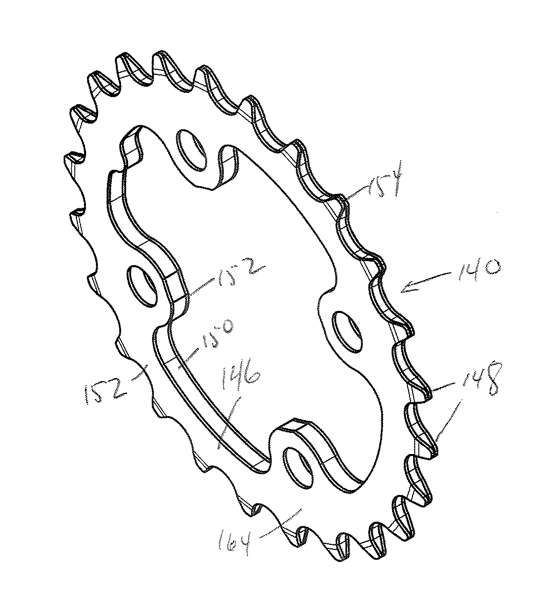
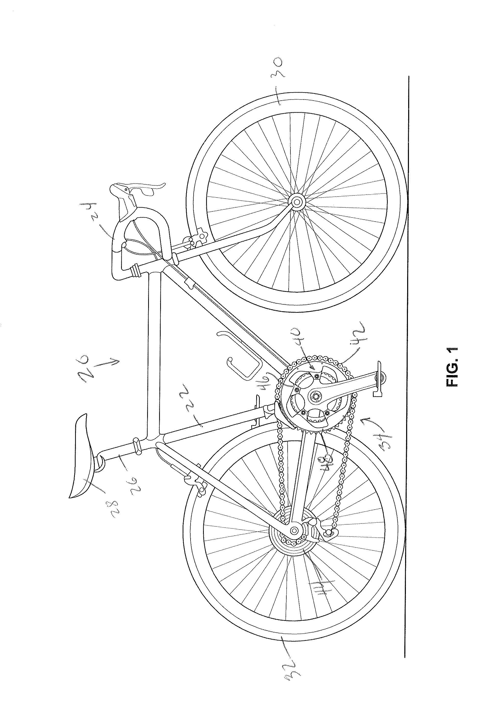
[0033]FIG. 1 is a standard bicycle 20 of standard construction. A frame 22 supports a handlebar 24 at a front end thereof and a seat post 26 and seat 28 at an upper part thereof. The frame 22 also rotatably carries two wheels: a front wheel 30 at a front of the bicycle 20 and a rear wheel 32 at a rear thereof. A drive train 34 drivingly connects pedals 36 to the rear wheel 32. The dr...


PUM


Abstract

A bicycle chainring, including a generally annular body formed of at least an inner material, the inner material including a first side and a second side opposite the first side and a plurality of teeth disposed about a periphery of the body. At least some of the plurality of teeth are formed of both the inner material and an outer material, the outer material disposed on one or both of the first and second sides, the outer material having a greater wear resistance relative to the inner material and a thickness greater than 0.1 millimeter.

Description

[0001]This application is a continuation of U.S. patent application Ser. No. 14 / 305,735, filed Jun. 16, 2014.BACKGROUND OF THE INVENTION[0002]This invention relates to chainrings for bicycles.[0003]Chainrings of standard bicycle drivetrains are most often made of steel or aluminum. Standard chainrings have a plurality of teeth disposed about the periphery thereof, all of which fit within the space defined by the link plates of an inner link of a standard bicycle roller chain. While some bicycle chainrings have used other materials, such as plastic or relatively exotic materials, these rings have not enjoyed commercial success due to inadequate performance properties or cost. Standard bicycle chainrings are also known that are plated and / or anodized in an attempt to improve wear performance and / or enhance the visual appearance of the chainrings. However, the material added to the chainrings is very thin—on the order of about 1-20 microns. Despite these beneficial modifications, plate...

Claims


Application Information

Patent Timeline
Patent Type & Authority Applications(United States)
IPC IPC(8): F16H55/30F16H55/06B62M9/10
CPCF16H55/30F16H55/06B62M9/10
Inventor WESLING, KEVINMEDAGLIA, ANTHONY
Owner SRAM CORPORATION
Why Eureka
Try Eureka