Transmission line

a transmission line and line technology, applied in the field of transmission lines, can solve the problems of reducing the distance between the signal conductors, and achieve the effect of reducing or preventing the coupling between a plurality of transmission lines and being convenient to manufactur

Active Publication Date: 2017-03-23
MURATA MFG CO LTD
View PDF0 Cites 9 Cited by
  • Summary
  • Abstract
  • Description
  • Claims
  • Application Information

AI Technical Summary

Benefits of technology

[0022]With this manufacturing method, the transmission line having the configuration described above is easily manufactured.
[0023]Various preferred embodiments of the present invention can provide a small-size transmission line in which coupling between a plurality of transmission lines is reduced or prevented.

Problems solved by technology

For example, when the configuration described above is used, narrowing the width of the transmission line leads to a reduced distance between the signal conductors, which are thus prone to being coupled to each other.

Method used


Image

  • Transmission line
  • Transmission line
  • Transmission line

Examples


Embodiment Construction

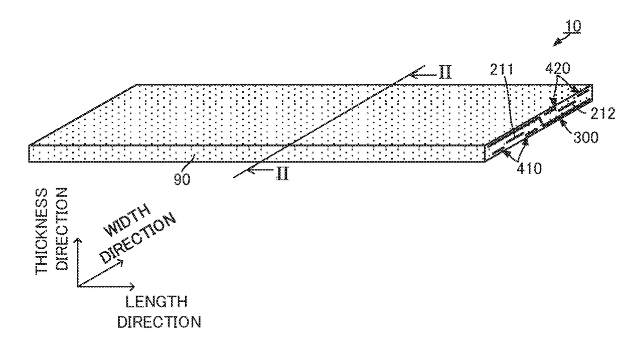
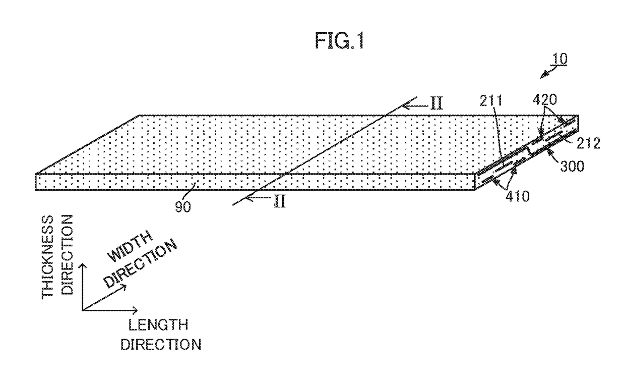
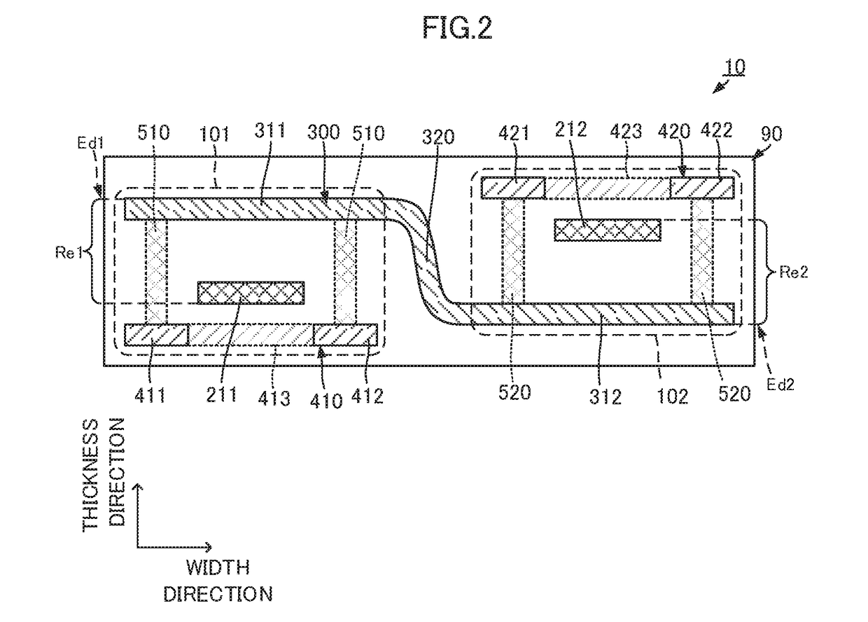
[0035]A transmission line according to a first preferred embodiment of the present invention and a method for manufacturing the transmission line will now be described with reference to the drawings. FIG. 1 is an external perspective view of a main portion of a transmission line according to the first preferred embodiment of the present invention. FIG. 2 is a cross-sectional view of the main portion of the transmission line according to the first preferred embodiment of the present invention. Specifically, FIG. 2 illustrates a cross-section taken along line II-II of FIG. 1. FIG. 3 is a plan view illustrating a configuration of each dielectric layer of the transmission line according to the first preferred embodiment of the present invention, and FIG. 4 is also a plan view illustrating a configuration of each dielectric layer of the transmission line according to the first preferred embodiment of the present invention. Specifically, FIG. 3 illustrates the fifth to seventh layers, and...


PUM


Abstract

A transmission line includes, in a dielectric body, a first ground conductor, and first and second signal conductors arranged in a width direction of the dielectric body. The first ground conductor includes a first signal conductor ground portion disposed closer to a first side of the dielectric body in a thickness direction than the first signal conductor, a second signal conductor ground portion disposed closer to a second side of the dielectric body in the thickness direction than the second signal conductor, and an intermediate portion that connects the first signal conductor ground portion to the second signal conductor ground portion. The intermediate portion is disposed between a first transmission line including the first signal conductor and the first signal conductor ground portion and a second transmission line including the second signal conductor and the second signal conductor ground portion.

Description

CROSS REFERENCE TO RELATED APPLICATIONS[0001]This application claims the benefit of priority to Japanese Patent Application 2014-116331 filed Jun. 5, 2014 and is a Continuation Application of PCT / JP2015 / 0659984 filed on Jun. 3, 2015. The entire contents of each application are hereby incorporated herein by reference.BACKGROUND OF THE INVENTION[0002]1. Field of the Invention[0003]The present invention relates to a transmission line in which signal conductors that transmit different high-frequency signals are located close to each other.[0004]2. Description of the Related Art[0005]Various types of transmission lines that transmit high-frequency signals have been proposed. For example, a transmission line described in Japanese Patent No. 4962660 has a stripline structure. The transmission line described in Japanese Patent No. 4962660 includes a long dielectric body, a signal conductor, and first and second ground conductors. The signal conductor is disposed in the middle of the dielect...

Claims


Application Information

Patent Timeline
Patent Type & Authority Applications(United States)
IPC IPC(8): H01P3/08H01P11/00
CPCH01P11/003H01P3/08H01P3/088H05K1/0224H05K2201/09672H01P3/085H05K1/02
Inventor BABA, TAKAHIROYOSUI, KUNIAKIIKEMOTO, NOBUOMATSUDA, FUMIE
Owner MURATA MFG CO LTD
Why Eureka
Try Eureka