Method of Using a Device Capable Of Controlled Flight

a technology of controlled flight and flight control, which is applied in the direction of process and machine control, instruments, additive manufacturing processes, etc., can solve the problems of limited range and type of structures that may be built, limit the size and scope of work they may act upon, etc., and achieve accurate and efficient building of structures.

Active Publication Date: 2017-04-27
IMPERIAL INNOVATIONS LTD
View PDF3 Cites 55 Cited by
  • Summary
  • Abstract
  • Description
  • Claims
  • Application Information

AI Technical Summary

Benefits of technology

[0023]The method may further comprise repeating the affixing step at least once. A subsequent affixing step may comprise affixing a further object held in the object-retaining means to an object already affixed to the target site. Thus, the device may be arranged to accurately and efficiently build a structure composed of objects that have been affixed to various target sites. A target site may be a site on an object that has already been affixed using the above-described method.
[0024]The object-retaining means may be arranged is pick up an object, and the method may further comprise using the object-retaining means to pick up an object Advantageously, therefore, the device may effectively build a structure entirely of objects found and picked up the surrounding environment. For example, the device may use the sensor means to generate sensor data of the environment. By processing the sensor using vision-based software algorithms known in the art, the device may identify and locate objects and pick them up using the object-retaining means. The objects may then be affixed to target sites and / or to each other in order to build a structure.

Problems solved by technology

However, traditional ground construction robots such as gantry and industrial robots are often constrained by predefined working areas that hinder their scale of action, and that limit the size and scope of pieces of work they may act upon.
In addition, the range and type of structures that may be built are limited.

Method used


Image

  • Method of Using a Device Capable Of Controlled Flight
  • Method of Using a Device Capable Of Controlled Flight
  • Method of Using a Device Capable Of Controlled Flight

Examples


Embodiment Construction

[0102]The present invention seeks to provide new and improved uses of aerial devices capable of controlled flight. Whilst various embodiments of the invention are described below, the invention is not limited to these embodiments, and variations of these embodiments may well fall within the scope of the invention which is to be limited only by the appended claims.

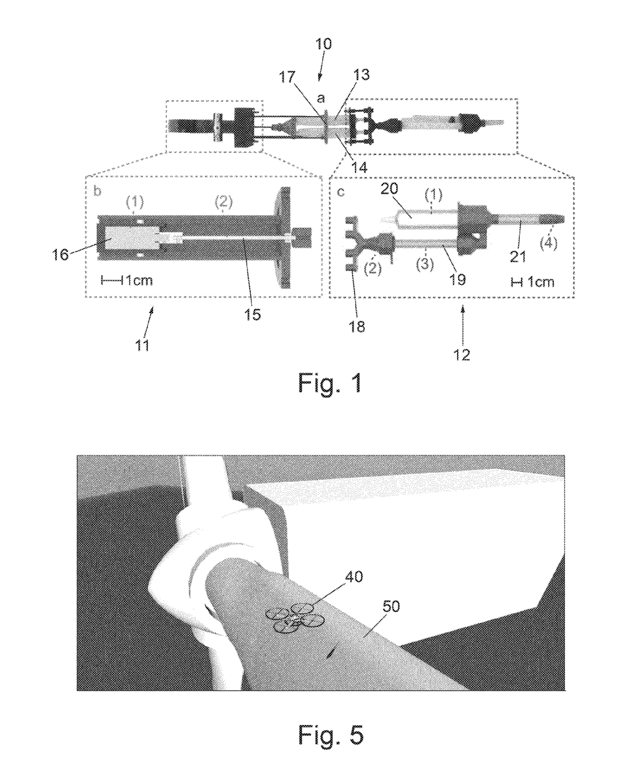
[0103]FIG. 1 illustrates a dispensing assembly 10 in accordance with an embodiment of the invention. As will be described in more detail below, dispensing assembly 10 is used to store, mix and dispense two or more chemicals that when combined produce an adhesive or other curable substance such as a foam.

[0104]Dispensing assembly 10 comprises actuator portion 11 and mixing portion 12. Actuator portion 11 and mixing portion 12 are each coupled to a pair of containers or reservoirs 13 and 14. Each reservoir 13 and 14 contains a chemical stored therein.

[0105]Actuator portion 11 comprises lead screw 15 driven by motor 16. Lead s...


PUM

PropertyMeasurementUnit
timeaaaaaaaaaa
timeaaaaaaaaaa
timeaaaaaaaaaa

Abstract

There is provided a method of using a device capable of controlled flight in a surrounding environment, the device comprising: lifting means for providing lift to the device; object-retaining means for holding an object to be affixed to a target site; and a dispensing assembly for dispensing an adhesive, wherein the method comprises: controlling the lifting means so as to controllably fly the device in the surrounding environment; and using the device to affix an object held by the object-retaining means to a target site in the surrounding environment by dispensing an adhesive from the dispensing assembly. Thus, an aerial device, for example a robotic device, may be used to fly to a desired location and affix an object at the desired location, by dispensing, ejecting or otherwise applying an adhesive.

Description

FIELD OF THE INVENTION[0001]The present invention relates to methods of using a device capable of controlled flight, and to such a device. In one embodiment, the invention relates to a method of affixing an object to a target site. The invention further relates to a dispensing assembly that may be used with the device.BACKGROUND TO THE INVENTION[0002]Robots are often used in the construction and architecture industries for fabrication purposes. Since the 1980s, mobile robots have been used to carry out assembly and construction tasks such as welding, painting, bricklaying and decommissioning. However, traditional ground construction robots such as gantry and industrial robots are often constrained by predefined working areas that hinder their scale of action, and that limit the size and scope of pieces of work they may act upon.[0003]The use of flying robots for carrying out construction tasks is a solution that overcomes some of the main limitations of predefined working areas face...

Claims


Application Information

Patent Timeline
Patent Type & Authority Applications(United States)
IPC IPC(8): B64C39/02G05D1/10B64C25/00
CPCB64C39/024B64C25/00G05D1/104B64C2201/108B64C2201/146B64D2211/00B64C2201/066B64C2201/042B64C2201/12B64C39/02F03D1/0675F03D80/50Y02E10/72B64U70/00B64U10/13B64U2101/00B29C64/00B29C64/106B29C48/00B05C11/1036B64D1/18B64U30/20B64U50/19B64U50/34B64U2201/20
Inventor KOVAC, MIRKOALHINAI, TALIB MUHAMMAD TALIB
Owner IMPERIAL INNOVATIONS LTD
Why Eureka
Try Eureka