Vehicular headlamp

Active Publication Date: 2017-05-18
TOYOTA JIDOSHA KK +1
View PDF7 Cites 4 Cited by
  • Summary
  • Abstract
  • Description
  • Claims
  • Application Information

AI Technical Summary

Benefits of technology

The present patent provides a vehicular headlamp that can appropriately distribute light without increasing its size. The headlamp has a structure wherein a first light source, a second light source, and a micro electro mechanical system mirror are held by a holding member, and the vehicle-front-side portions of the first and second light distribution portions are constituted by a single lens. Additionally, a separating wall protruding towards the vehicle front side is formed in the holding member to shield the light projected by the first light source and reflected by the micro electro mechanical system mirror, thus preventing it from passing through a portion of the lens and ensuring appropriate light distribution in both the first and second light distribution portions. The position of the separating wall can be adjusted to enhance the light shielding effect.

Problems solved by technology

This causes a problem of upsizing of the vehicular headlamp.
This may make it difficult to perform light distribution in each unit appropriately.

Method used


Image

  • Vehicular headlamp
  • Vehicular headlamp
  • Vehicular headlamp

Examples


Embodiment Construction

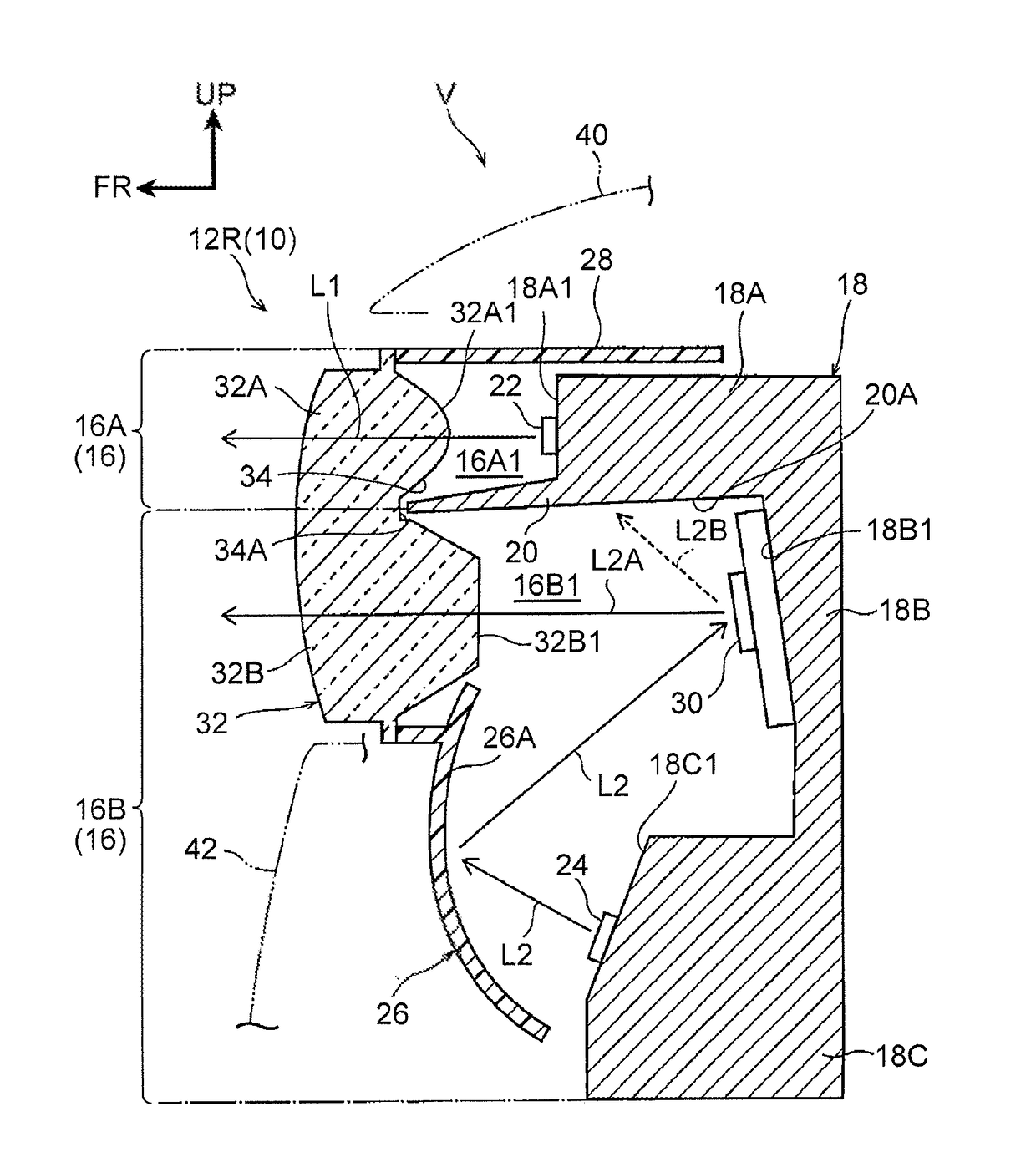
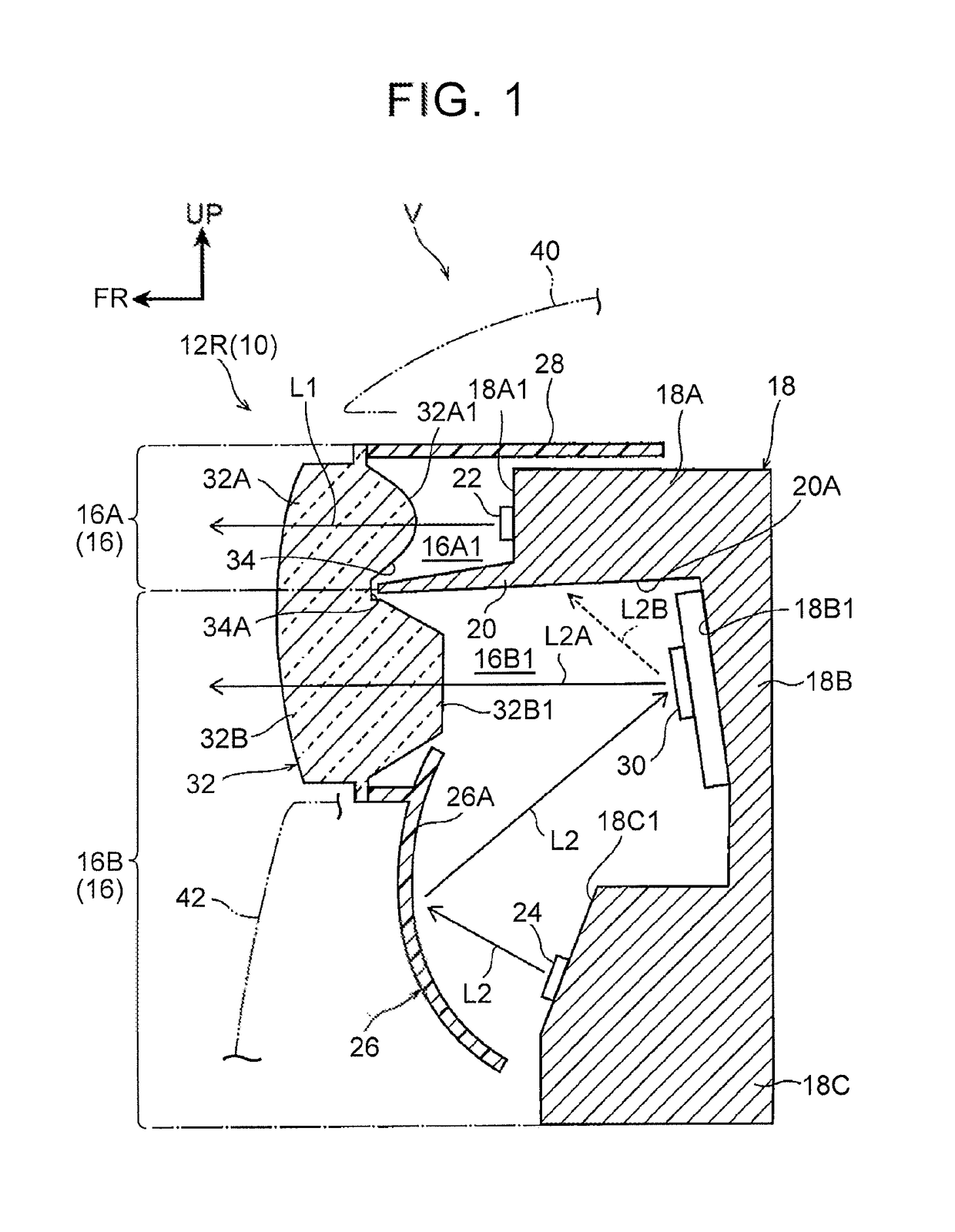
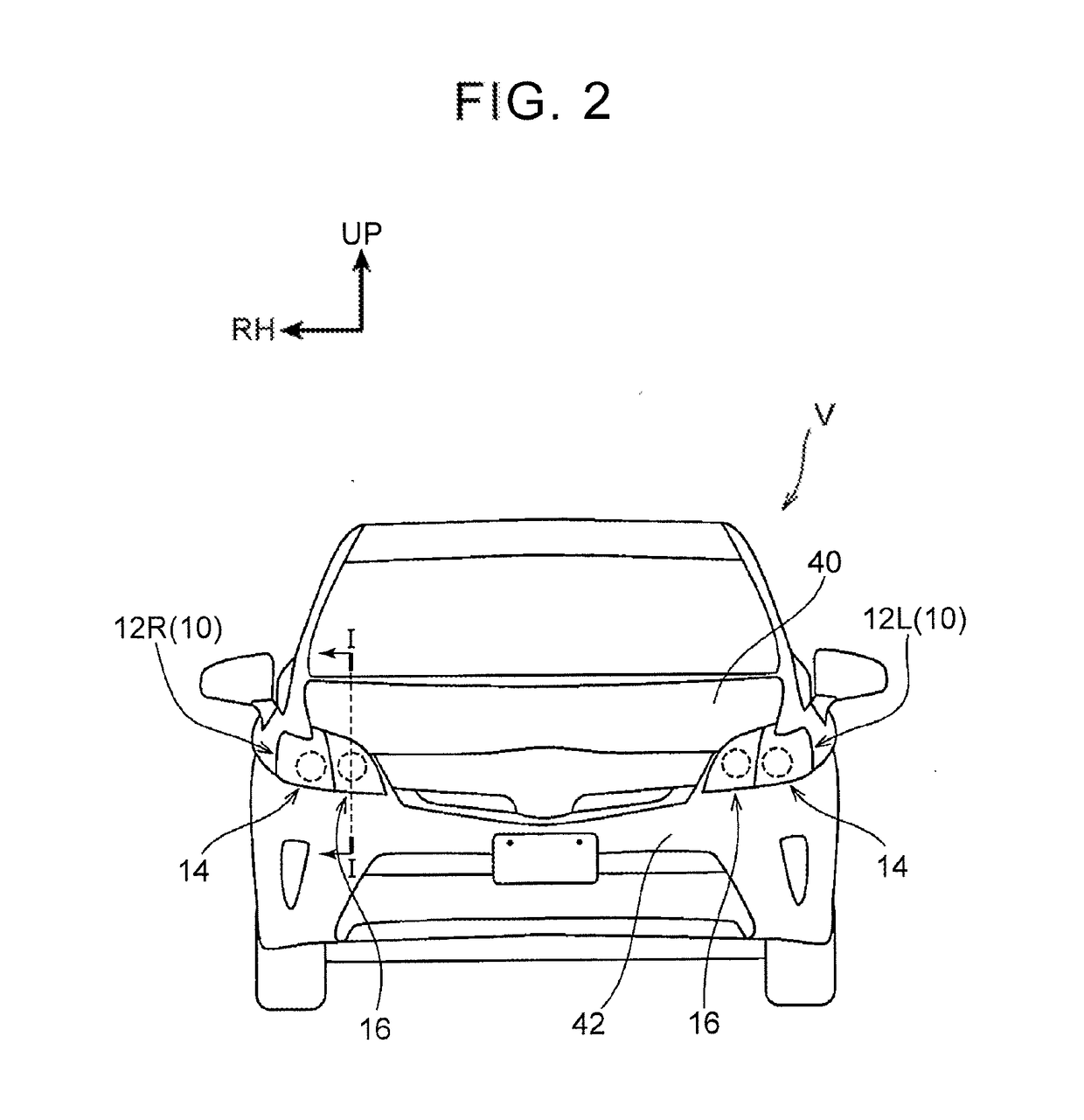
[0025]A vehicular headlamp 10 according to the present embodiment is described below with reference to the drawings. Note that an arrow UP and an arrow FR illustrated in the drawings indicate a vehicle upper side and a vehicle front side of a vehicle V to which the vehicular headlamp 10 is applied, respectively, and an arrow RH illustrated in the drawings indicates a vehicle right side in a state where the vehicle V faces a travelling direction. Hereinafter, in a case where a description is made by use of merely an up-down direction, a front-rear direction, and a right-left direction, they indicate up and down of a vehicle up-down direction, front and rear of a vehicle front-rear direction, and right and left in a vehicle right-left direction (a vehicle width direction), respectively, unless otherwise specified.

[0026]As illustrated in FIG. 2, the vehicular headlamp 10 includes a pair of head lamp units 12R, 12L on right and left sides. The head lamp unit 12R is placed in a right end...


PUM


Abstract

A vehicular headlamp includes: a first light distribution portion including a first light source; a second light distribution portion including a second light source and an micro electro mechanical system mirror; a holding member configured to hold the first light source, the second light source, and the micro electro mechanical system mirror; a single lens including a first lens portion and a second lens portion; and a separating wall formed in the holding member so as to protrude toward the vehicle front side relative to the holding member, the separating wall being configured to separate a region between the first lens portion and the holding member from a region between the second lens portion and the holding member.

Description

INCORPORATION BY REFERENCE[0001]The disclosure of Japanese Patent Application No. 2015-222269 filed on Nov. 12, 2015 including the specification, drawings and abstract is incorporated herein by reference in its entirety.BACKGROUND[0002]1. Technical Field[0003]The present disclosure relates to a vehicular headlamp.[0004]2. Description of Related Art[0005]A vehicular headlamp described in Japanese Patent Application Publication No. 2015-38885 (JP 2015-38885 A) includes a fixed light distribution unit and a variable light distribution unit. On this account, the variable light distribution unit can form various light distribution patterns and project light with the light distribution patterns toward a vehicle front side.SUMMARY[0006]However, in the vehicular headlamp of the related art, the fixed light distribution unit and the variable light distribution unit formed separately are arranged side by side in a vehicle up-down direction. This causes a problem of upsizing of the vehicular h...

Claims


Application Information

Patent Timeline
IPC IPC(8): B60Q1/076F21V14/04F21S8/10F21W107/10
CPCB60Q1/076F21S48/1305F21V14/04F21S48/328F21S48/1225F21V13/04F21S41/20F21W2102/00F21W2107/10F21S41/143F21S41/147F21S41/16F21S41/162F21S41/172F21S41/18F21S41/265F21S41/36F21S41/365F21S41/39F21S41/43F21S41/47F21S41/663F21S41/675F21S45/47F21S41/285
Inventor MOURI, FUMIHIKONAKADA, YUSUKENAKANISHI, YOSHIYUKI
Owner TOYOTA JIDOSHA KK
Why Eureka
Try Eureka