Method and arrangement for burning lime mud

a technology of lime mud and combustion chamber, which is applied in the field of method and arrangement for burning lime mud, can solve the problems of high combustion air requirement, high energy consumption, and inability to prove the quality of lime produced and combustion costs as advantageous, and achieve the effect of improving the energy economy of gasifier/lime kiln arrangement and efficiently utilizing the thermal energy being released

Active Publication Date: 2017-10-12
ANDRIZ OY
View PDF12 Cites 0 Cited by
  • Summary
  • Abstract
  • Description
  • Claims
  • Application Information

AI Technical Summary

Benefits of technology

[0016]A method and system have been invented to improve the energy economy of a gasifier / lime kiln arrangement. Especially the method and system more efficiently utilizes the thermal energy being released in the lime kiln, when the fuel used in the lime kiln is fuel gas produced in a separate gasifier.
[0019]According to an embodiment of the invention, a conduit is arranged between the gasifier and the firing end of the lime kiln, via which conduit secondary air from the lime kiln is led into the gasifier. The conduit is provided with a fan or corresponding for withdrawing air from the kiln. The conduit extends through the firing end to a suitable distance to the interior of the kiln. According to a preferred embodiment the combustion air for the gasifier is withdrawn from the depth of the so-called kiln dam or from almost the level of the burner inside the kiln. As known, for improving heat transfer the breast is mounted at the hot end of the kiln proximate to the lime discharge zone. The dam is formed by tapering the diameter of the kiln housing or by thickening the refractory lining of the kiln.
[0020]The cooler is surrounded by a stationary cylindrical radiation shield that is insulated from the outer side and at one end tightly connected to a cooled lime discharge hopper, through which the lime exits the kiln. The function of the radiation shield is to act as thermal insulation outwards and to prevent dust leakages. One end of the radiation shield is partly open, and the cooling air is withdrawn into the cooler through a gap between that end and the burner end of the kiln. Most of the cooling air is led through a canal between the kiln housing and the inner casing of the cooler into the interior of the cooler to a sector portion, where cooling of the lime takes place according to the counter-current principle. A smaller portion of the air is guided through the gap between the radiation shield and the cooler into the canal between them. From this canal the air heated by the hot lime can be led as combustion air into the gasifier. This is one embodiment for obtaining combustion air for gasification through the housing of the lime kiln. Thereby a temperature of approximately 200° C. is obtainable.
[0028]By taking the combustion air for the gasifier through a cooler, the operation of the cooler is intensified and the temperature of the lime exiting therefrom is decreased. That is, a greater portion of the heat of the exiting lime is recovered in combustion air.
[0029]Intensified cooling is an advantage as such, which assists in further treatment of the lime and protects the cooler against damages and blockages caused by high temperature. Additionally, the cooling air for the lime can be withdrawn along the kiln housing, whereby a function of the air is also to cool the kiln housing. By withdrawing more air, also the cooling of the housing is intensified.

Problems solved by technology

Other lime burning methods exist, but the quality of the lime produced and the combustion costs have not been proved as advantageous as those of lime produced in a rotary kiln.
Lime mud combustion is characterized by high consumption of energy and thus high combustion air requirement.
A problem in the use of coal is that molten slag generated in the combustion adheres in the interior of the lime kiln and forms rings that may clog the flow in the kiln.
This results e.g. in increase in the specific heat consumption in lime combustion, since it is not possible to utilize the energy content of the fuel to an adequately large extent for promoting the calcination reaction.
Then it is not possible to utilize all the heat of the flue gas in lime mud preheating, but an increased portion of the heat escapes the process due to the increased temperature of the flue gas.
When the adiabatic temperature of the flame remains low, the nominal production of the kiln can in an extreme case be unreached, since calcination does not proceed far enough with full-scale production.
Further, increased flue gas amount can limit the production of the kiln when the auxiliary devices, such as a flue gas fan remain too small.
The product gas of gasification has been used as energy source for lime kilns since the end the 1980-es, but due to the low price of oil and mineral coal it has not gained high popularity.
Alternatively the combustion air can be heated with steam exchangers, but also then valuable energy is to be consumed.

Method used


Image

  • Method and arrangement for burning lime mud
  • Method and arrangement for burning lime mud
  • Method and arrangement for burning lime mud

Examples


Embodiment Construction

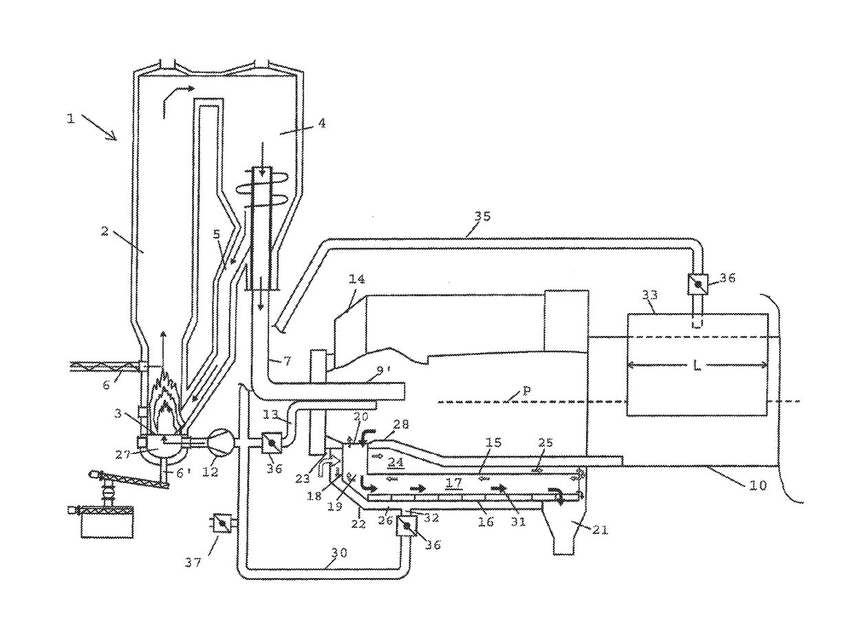
[0036]FIG. 1 illustrates components of a lime mud combustion plant and a gasifier that are needed for describing the invention. The gasification unit is in this case a circulating fluidized bed gasifier 1, i.e. a CFB-gasifier. It comprises a gasification reactor 2, a grate 3, a cyclone 4 and a cyclone return pipe 5. A fluidized bed is arranged at the lower part of the gasifier, above which bed a fuel is introduced. The fuel is typically solid bio-based fuel 6, such as bark, wood chips etc. Ash generated in the gasification is removed via conduit 6′.

[0037]The hot product gas exits the gasifier via duct 7 and is partially cooled in an air preheater 8. Then the product gas is led into a burner 9 of the lime kiln 10 via the gas duct 7.

[0038]In this known arrangement, the combustion air for the gasifier is introduced by means of a fan 11 from ambient conditions. Prior to feeding into the gasifier, the air is heated typically to 300-400° C. by cooling hot product gas from the gasifier in ...


PUM

PropertyMeasurementUnit
surface temperatureaaaaaaaaaa
temperatureaaaaaaaaaa

Abstract

An arrangement for burning lime mud into lime in a lime kiln. The lime mud flows counter-currently to flue gases from a feed end to a firing end and the fuel used is flue gas that is produced by gasifying a fuel in the presence of combustion air in a gasifier. The combustion air for gasification is preheated with heat generated in lime mud combustion. The arrangement is provided with a conduit between the lime kiln and the gasifier for leading air from the lime kiln into the gasifier as combustion air. At least a portion of the combustion air for gasification is preheated with heat generated in the lime mud combustion so that air is led into cooling of lime obtained in the combustion and further into the kiln, from or through the firing end of which air is taken into the gasification.

Description

RELATED APPLICATIONS[0001]This application is a divisional of U.S. patent application Ser. No. 14 / 001,466 filed Nov. 1, 2013 (now U.S. Pat. No. 9,643,885) which is the U.S. national phase of International Application No. PCT / FI2012 / 050186 filed 23 Feb. 2012 which designated the U.S. and claims priority to FI 20115198 filed 28 Feb. 2011, the entire contents of each of which are hereby incorporated by reference.BACKGROUND[0002]The present invention relates to a method and an arrangement for burning lime mud into lime in a lime kiln wherein the lime mud flows counter currently in relation to flue gases from a feed end into a firing end and wherein fuel gas is used as fuel, which gas is produced by means of gasification of a fuel in the presence of combustion air in a gasifier.[0003]Typically, the lime mud formed in a recovery process of the chemical pulp industry is burned into lime (calcium oxide) and carbon dioxide in a rotary kiln. Other lime burning methods exist, but the quality o...

Claims


Application Information

Patent Timeline
Patent Type & Authority Applications(United States)
IPC IPC(8): C04B2/10F27D17/00F27B7/36C04B2/00F27B7/20
CPCC04B2/108C04B2/005F27D17/004F27B7/36F27B7/20C10J3/56C10J2300/0956C10J2300/1606C10J2300/1869C04B2/10Y02P20/129Y02P40/40D21C11/12
Inventor VEHMAAN-KREULA, JUHANI
Owner ANDRIZ OY
Why Eureka
Try Eureka