Dish antenna and method for manufacturing bracket thereof

a technology of dish antenna and bracket, which is applied in the direction of antennas, antenna details, electrical equipment, etc., can solve the problems of limited cost and the inability to reduce the weight of the dish antenna, and achieve the effects of reducing the dimensions of the planar bracket substrate (raw metal plate), preserving the structural strength of the dish antenna, and reducing the cost of the brack

Active Publication Date: 2018-07-26
WISTRON NEWEB
View PDF4 Cites 4 Cited by
  • Summary
  • Abstract
  • Description
  • Claims
  • Application Information

AI Technical Summary

Benefits of technology

[0007]Utilizing the embodiment of the invention, the first wing plate and the second wing plate are folded toward the transverse direction, namely about the longitudinal direction of the bracket. Therefore, the dimensions of the planar bracket substrate (raw metal plate) are decreased, the cost of the bracket is reduced, and the structural strength thereof is maintained.

Problems solved by technology

In the conventional concept, when pressure is exerted on the dish antenna by the wind, the dish antenna must have sufficient structural strength, and the possibility to reduce the weight and the cost of the dish antenna is limited.

Method used


Image

  • Dish antenna and method for manufacturing bracket thereof
  • Dish antenna and method for manufacturing bracket thereof
  • Dish antenna and method for manufacturing bracket thereof

Examples


Embodiment Construction

[0021]The following description is of the best-contemplated mode of carrying out the invention. This description is made for the purpose of illustrating the general principles of the invention and should not be taken in a limiting sense. The scope of the invention is best determined by reference to the appended claims.

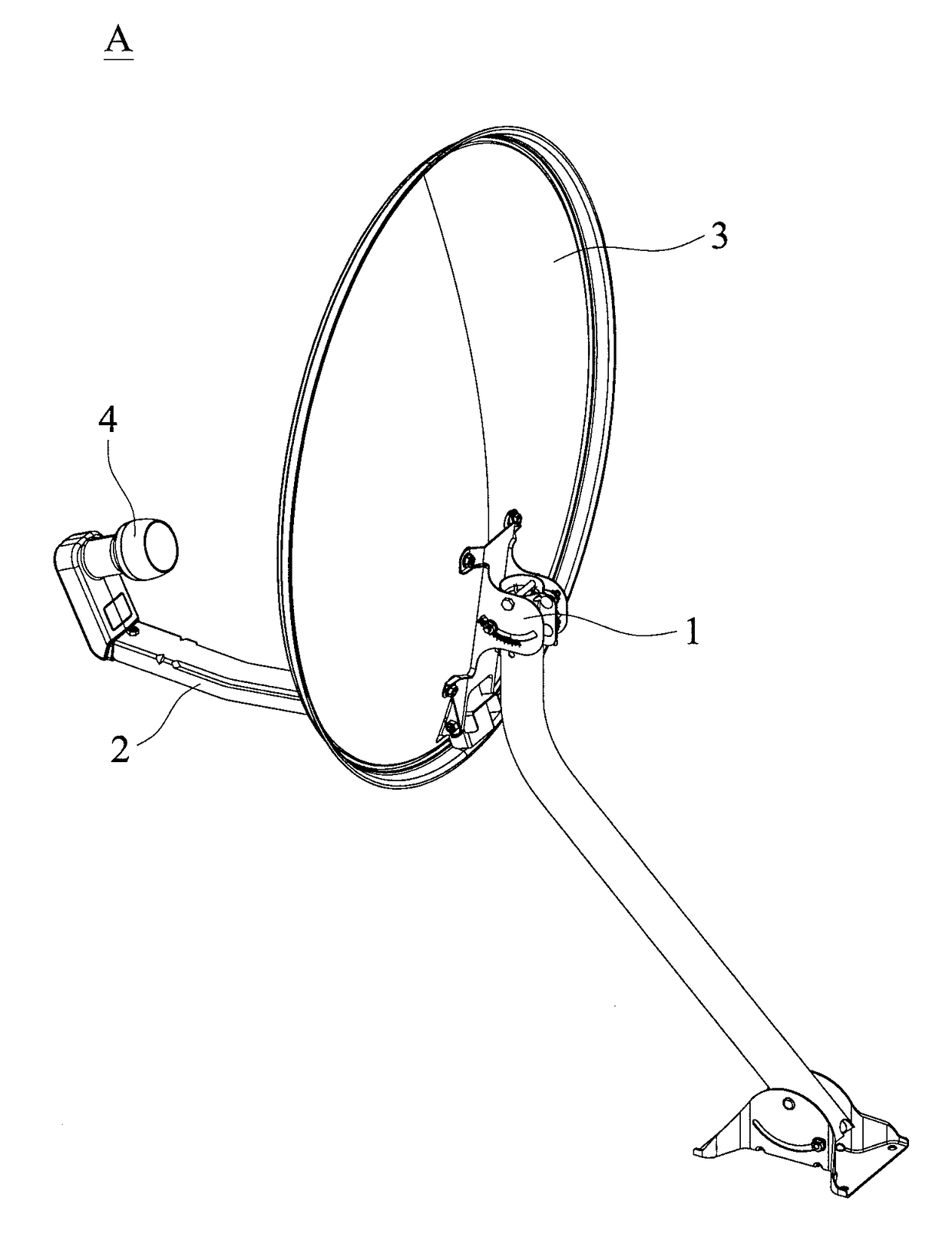
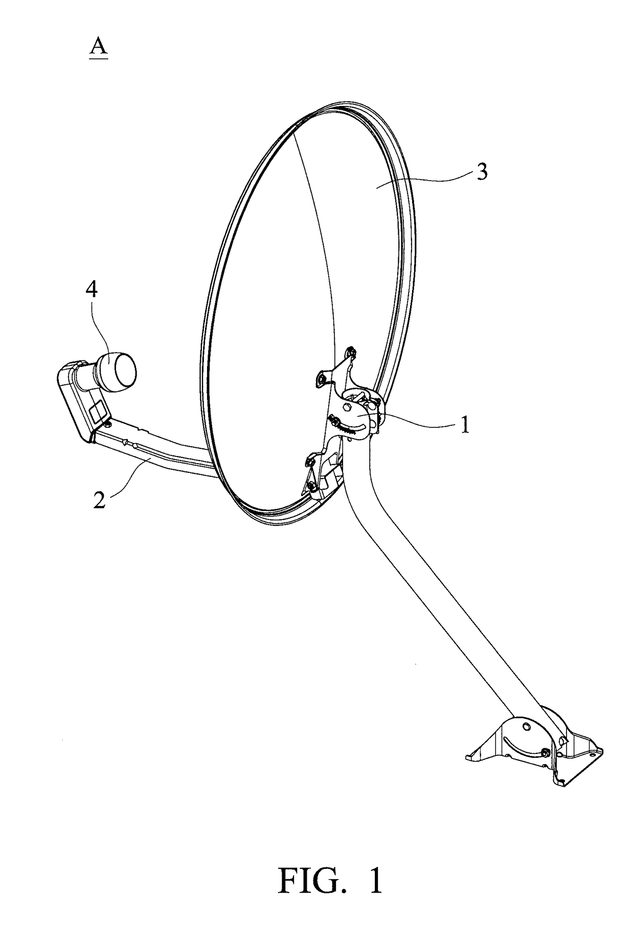
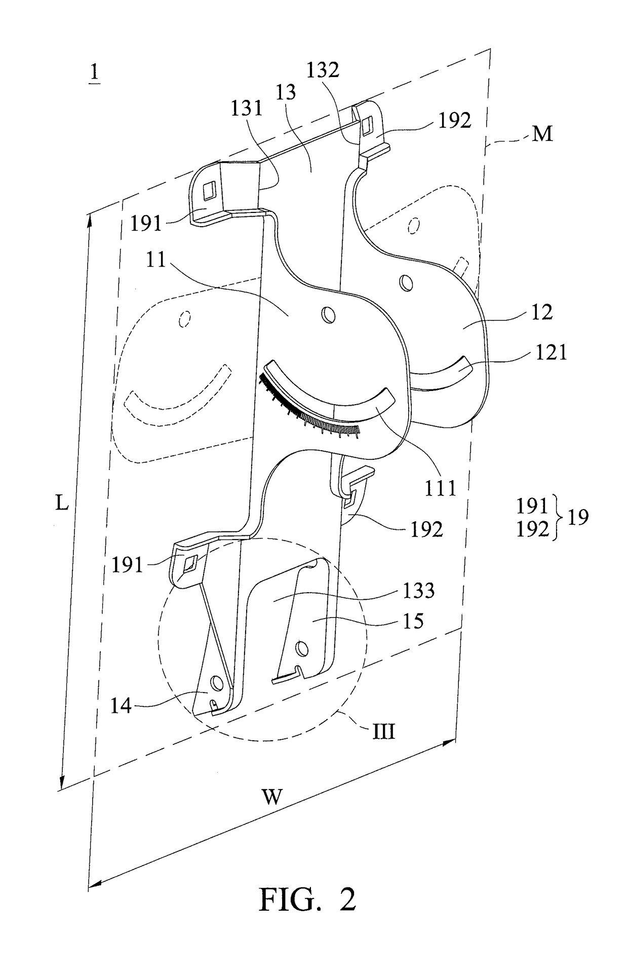
[0022]FIG. 1 shows a dish antenna A of an embodiment of the invention. The dish antenna A includes a dish 3, a bracket 1, a supporter 2 and a receiver 4. The bracket 1 is connected to the dish 3. The supporter 2 is connected to the bracket 1. The receiver 4 is connected to the supporter 2 and corresponds to the dish 3. With reference to FIG. 2, the bracket 1 includes a base 13, a first wing plate 11, a second wing plate 12 and a plurality of fastening portions 19. An aspect of the base 13 faces the dish 3. The bracket 1 is affixed to the dish 3 through the fastening portions 19. The first wing plate 11 is disposed on a first side 131 of the base 13. The second wing pla...


PUM


Abstract

A dish antenna is provided. The dish antenna includes a dish, a bracket, a supporter and a receiver. The bracket is connected to the dish. The supporter is connected to the bracket. The receiver is connected to the supporter and corresponding to the dish. The bracket includes a base, a first wing plate, a second wing plate and a plurality of fastening portions. The base faces the dish. The bracket is affixed to the dish through the fastening portions. The first wing plate is disposed on a first side of the base. The second wing plate is disposed on a second side of the base. The first side is opposite to the second side. The first wing plate, the second wing plate and the fastening portions are integrally formed with the base.

Description

BACKGROUND OF THE INVENTIONField of the Invention[0001]The present invention relates to a dish antenna, and in particular to a dish antenna having reduced cost.Description of the Related Art[0002]The conventional dish antenna includes a dish, a bracket, a supporter and a receiver. The bracket is cut and punched from a raw metal plate. The bracket includes two wing plates. The wing plates are fold along a longitudinal direction of the bracket. FIG. 11 shows the conventional bracket (spread out state) C1. Conventionally, as shown in FIG. 11, the dimensions of the raw metal plate (the wing plates are spread out in the longitudinal direction) are about 13 cm x 51 cm. The supporter is a metal tube with a rectangular cross section. The supporter is formed by a punching and welding process.[0003]In the conventional concept, when pressure is exerted on the dish antenna by the wind, the dish antenna must have sufficient structural strength, and the possibility to reduce the weight and the co...

Claims


Application Information

Patent Timeline
Patent Type & Authority Applications(United States)
IPC IPC(8): H01Q1/12H01Q15/16H01Q3/06
CPCH01Q1/1207H01Q3/06H01Q15/16H01Q1/12H01Q1/125H01Q3/02H01Q19/132
Inventor YANG, LAN-CHUNWANG, CHUN-WEIKUO, SHUN-CHUNGKUO, SAN-YI
Owner WISTRON NEWEB
Why Eureka
Try Eureka