Display device and driving method

a technology of display device and driving method, which is applied in the direction of optics, instruments, optical light guides, etc., can solve the problems of reducing the image resolution as perceived by the viewer, the user has to be at a fixed position, and the barrier arrangement is simple to produce but not light efficient, so as to speed up the recovery of photochromic material, prevent the exposure of the user of the device, and increase the speed of response of light blocking elements

Active Publication Date: 2018-09-13
KONINKLJIJKE PHILIPS NV
View PDF3 Cites 56 Cited by
  • Summary
  • Abstract
  • Description
  • Claims
  • Application Information

AI Technical Summary

Benefits of technology

[0033]A UV filter may be provided at the display panel output. This is used to prevent exposure of the user of the device to the UV light generated by the backlight, and also to prevent ambient UV light reaching the light blocking elements and thereby inducing undesired switching.
[0034]The third output, for inducing switching of the light blocking elements towards a transparent state, is used to increase the speed of response of the light blocking elements, in particular for switching to the transparent state. The third output is preferably a non-visible light output, for example an IR light output. This is used to induce heating, which can speed up the recovery of the photochromic material.

Problems solved by technology

A drawback of this type of two-view display design is that the viewer has to be at a fixed position, and can only move approximately 3 cm to the left or right.
The barrier arrangement is simple to produce but is not light efficient.
Increasing the number of views improves the 3D impression but reduces the image resolution as perceived by the viewer, since all views are displayed at the same time by the native display.
The end result is a display with a large viewing angle, although viewers are not entirely free in choosing their location from which to view the 3D monitor or television: at the boundaries between viewing cones the 3D effect is absent and ghost images appear.
This wide viewing angle is a problem in situations where the user of the display would prefer no eavesdropping on all or certain parts of the display content.
The light blocking structures are however potentially difficult to manufacture, as they are vertical structures.

Method used


Image

  • Display device and driving method
  • Display device and driving method
  • Display device and driving method

Examples


Embodiment Construction

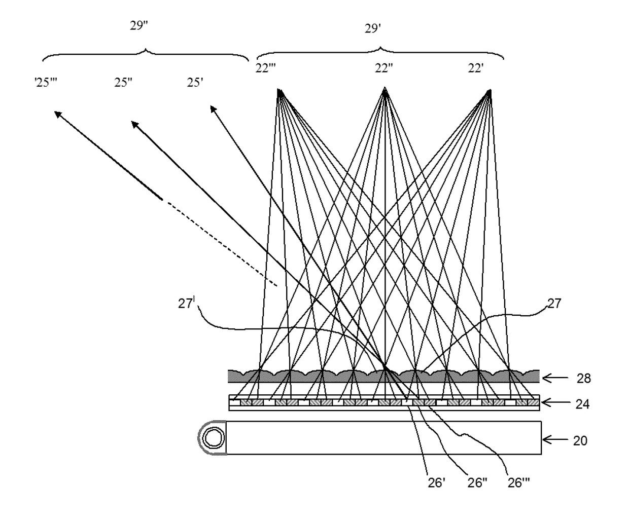
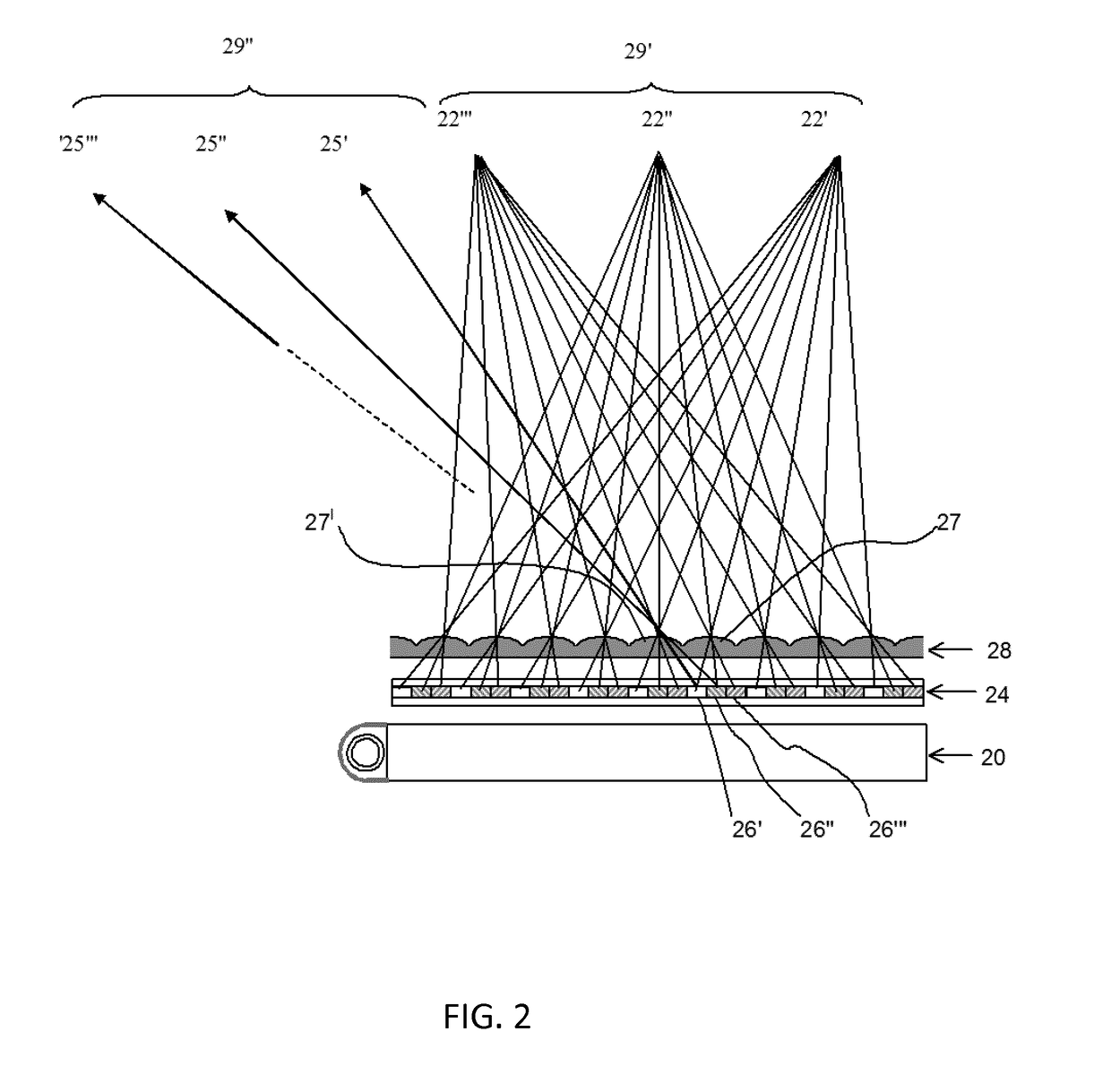
[0062]The invention provides a display device that has a light blocking arrangement for selectively blocking light which has or would be emitted at large lateral angles. The display can be configured so that light reaching these elements is either allowed to reach the viewer or is blocked from reaching the viewer. This means that a public viewing mode can be chosen or a private viewing mode. The light blocking elements are controlled optically in order to simplify the construction and control.

[0063]The invention will be described with reference to an autostereoscopic display device, but it can be used generally to provide a private and a public viewing mode.

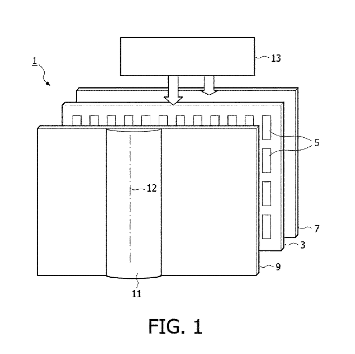
[0064]FIG. 1 is a schematic perspective view of a known direct view autostereoscopic display device 1. The known device 1 comprises a liquid crystal display panel 3 of the active matrix type that acts as a spatial light modulator to produce the display.

[0065]The display panel 3 has an orthogonal array of display sub-pixels 5 arra...


PUM

PropertyMeasurementUnit
lateral emission angleaaaaaaaaaa

Abstract

A display device has a light blocking arrangement for selectively blocking light which has or would be emitted at large lateral angles. The display can be configured so that light reaching these elements is either allowed to reach the viewer or is blocked from reaching the viewer. This means that a public viewing mode can be chosen or a private viewing mode. The light blocking elements are controlled optically in order to simplify the construction and control.

Description

FIELD OF THE INVENTION[0001]This invention relates to a display device which is able to provide a privacy mode and a public mode. It relates particularly but not exclusively to an autostereoscopic display device with a display panel having an array of display pixels for producing a display and an imaging arrangement for directing different views to different spatial positions.BACKGROUND OF THE INVENTION[0002]A first example of an imaging arrangement for use in an autostereoscopic display device of this type of display is a barrier, for example with slits that are sized and positioned in relation to the underlying pixels of the display. In a two-view design, the viewer is able to perceive a 3D image if his / her head is at a fixed position. The barrier is positioned in front of the display panel and is designed so that light from the odd and even pixel columns is directed towards the left and right eye of the viewer, respectively.[0003]A drawback of this type of two-view display design...

Claims


Application Information

Patent Timeline
Patent Type & Authority Applications(United States)
IPC IPC(8): G02F1/13F21V8/00G02F1/1335G02B27/22G02B30/27
CPCG02F1/1323G02B6/0051G02F1/133617G02B6/0068G02F1/133512G02B27/2214G02F2202/14G02F2203/62G02B30/27
Inventor KROON, BART
Owner KONINKLJIJKE PHILIPS NV
Why Eureka
Try Eureka