Controller

a control board and backboard technology, applied in the field of control boards, can solve problems such as wrong connection of circuit board units to be connected, and achieve the effect of preventing the wrong connection of each control board to the backboard

Inactive Publication Date: 2019-05-02
FANUC LTD
View PDF14 Cites 6 Cited by
  • Summary
  • Abstract
  • Description
  • Claims
  • Application Information

AI Technical Summary

Benefits of technology

The present invention aims to prevent incorrect connection between control boards and backboards. This is achieved by shifting the attachment position of the first connector on each control board. The technical effect of this invention is to ensure accurate connection between control boards and backboards, thereby improving the overall efficiency and reliability of electronic control systems.

Problems solved by technology

In the invention described in Japanese Laid-Open Patent Publication No. 07-086774, however, since the printed circuit board units have the same size, there is a possibility that a printed circuit board unit to be connected is wrongly connected to the backboard by inserting it into incorrect guide grooves which are assigned to another printed circuit board unit.

Method used


Image

  • Controller
  • Controller
  • Controller

Examples


Embodiment Construction

[0036]A controller according to the present invention will be detailed hereinbelow by describing preferred embodiments with reference to the accompanying drawings.

[Schematic Configuration of Controller 10 and Display Device 12]

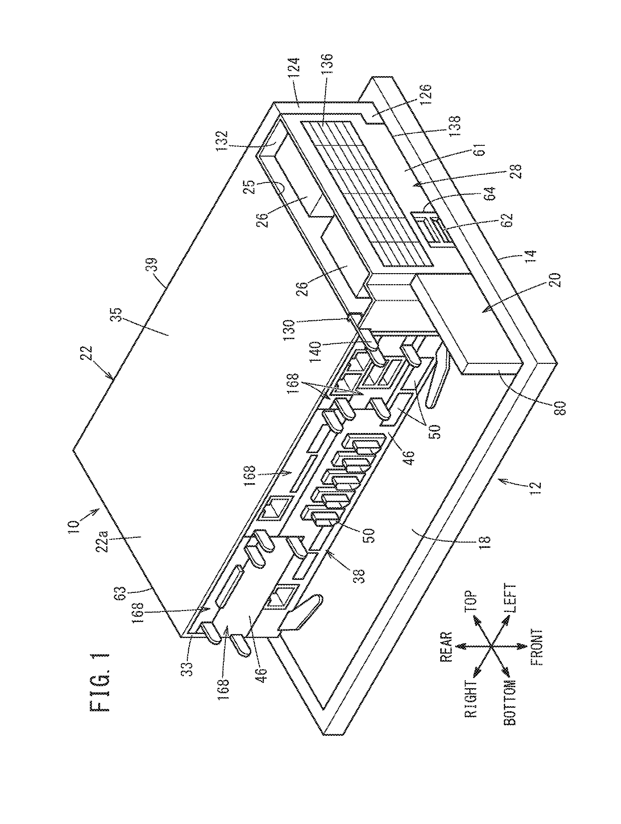
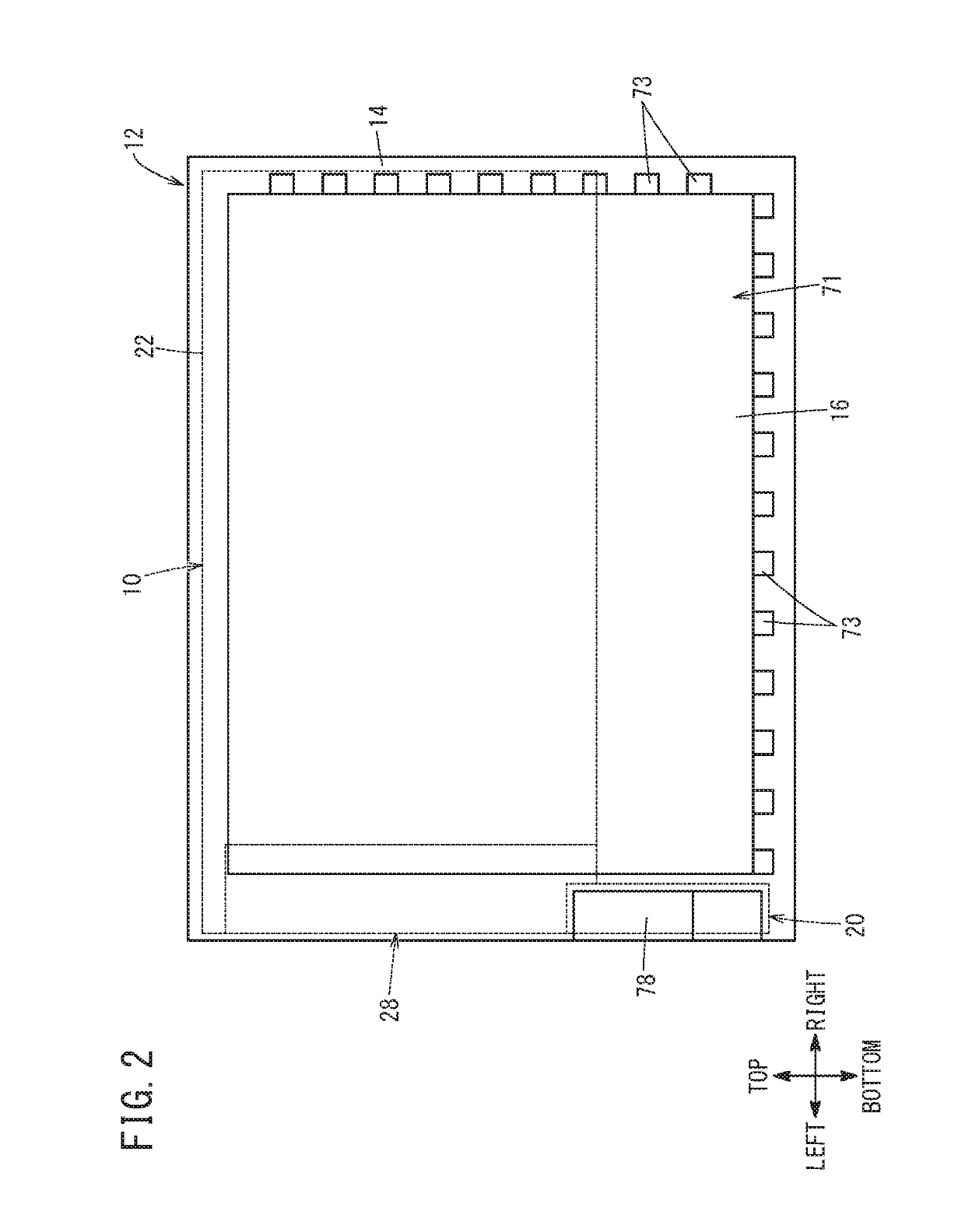
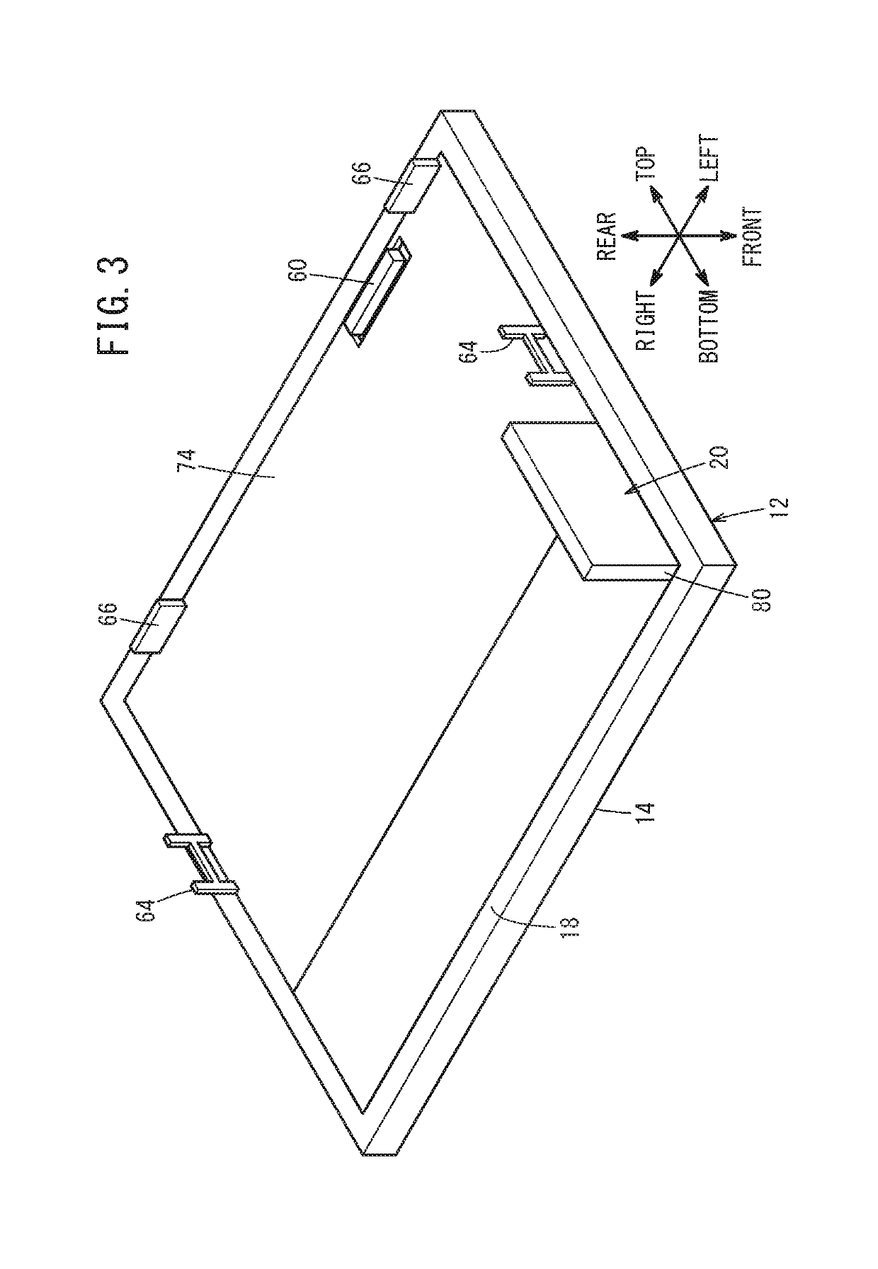
[0037]A schematic configuration of a controller 10 according to the present embodiment and a display device 12 will be described with reference to FIGS. 1 to 5.

[0038]The controller 10 is a control device for controlling the display device 12. The display device 12 is a liquid crystal display unit having a display screen 16 (see FIG. 2) arranged on the front face, designated at 14. Note that the display device 12 may be another type of display unit. The controller 10 may be applied to, for example, a numerical control device for a CNC (computer numerical control) machine tool. In this case, the display device 12 is provided for the operation panel of the machine tool. In the following description, the directions of up and down, right and left, and front and rea...


PUM


Abstract

A controller includes: a housing; a plurality of control boards accommodated in a plurality of slots formed in the housing, in a manner that the control boards are insertable into and removable from the slots; a backboard provided inside the housing on an interior side with respect to a direction of insertion of the plurality of control boards; and a plurality of junctions provided to establish electric connection between the plurality of control boards inserted into the slots and the backboard. Each of the junctions includes a first connector attached to the control board and a second connector attached to the backboard so as to be connected to the first connector. Attachment positions of the plurality of first connectors relative to the control boards are configured to differ from each other when the first connectors are viewed from the direction of insertion of the control boards.

Description

CROSS-REFERENCE TO RELATED APPLICATION[0001]This application is based upon and claims the benefit of priority from Japanese Patent Application No. 2017-210485 filed on Oct. 31, 2017, the contents of which are incorporated herein by reference.BACKGROUND OF THE INVENTIONField of the Invention[0002]The present invention relates to a controller including a plurality of control boards accommodated in a plurality of slots that are formed in a housing, such that the control boards are insertable into and removable from the slots.Description of the Related Art[0003]Japanese Laid-Open Patent Publication No. 07-086774 discloses a configuration in which printed circuit board units (control boards) are inserted into guide grooves in a housing unit, and in which each of the printed circuit board units is connected to a backboard with connectors.SUMMARY OF THE INVENTION[0004]In the invention described in Japanese Laid-Open Patent Publication No. 07-086774, however, since the printed circuit board...

Claims


Application Information

Patent Timeline
Patent Type & Authority Applications(United States)
IPC IPC(8): H05K1/14H05K5/02
CPCH05K1/141H05K5/026H05K5/0291H05K7/1481G05B19/409
Inventor YOSHIDA, KOUHEIKOBAYASHI, HIDEOSUWA, HIROYUKISAKAMOTO, JUNICHI
Owner FANUC LTD
Why Eureka
Try Eureka