Eureka AIR delivers breakthrough ideas for toughest innovation challenges, trusted by R&D personnel around the world.

Rigid endoscope

a technology of endoscopes and endoscopes, which is applied in the field of rigid endoscopes, can solve the problems of varying thermal expansion of fiber image guides and surrounding shaft tubes, inability to detach, and inability to accurately align the optical system

Active Publication Date: 2019-05-30
OLYMPUS WINTER & IBE
View PDF0 Cites 0 Cited by
  • Summary
  • Abstract
  • Description
  • Claims
  • Application Information

AI Technical Summary

Benefits of technology

The patent text aims to improve the attachment of a fiber image guide in a sliding element to improve precision and preservation of the fibers. The technical effect is to provide a more robust and secure attachment of the fiber image guide in a space-saving manner without compromising its performance.

Problems solved by technology

The generic endoscopes with their completely bend insensitive fiber image guide can be bent without risk, but have system-related disadvantages, such as, the varying thermal expansion of the fiber image guide and the surrounding shaft tube.
Even the non-centric mounting of the fiber image guide in the shaft tube can lead to longitudinal displacements during bending, through which the precise alignment of the optical system is disturbed.
An adhesion, for example, could be made here, with the great disadvantage that this attachment is not detachable and thus the fiber image guide cannot or only with great difficulty be dismantled.
Here, however, there is immediately the great risk of damage to the fibers or the clamping forces are reduced to such an extent that there is a risk of slipping.
However, such twisting sections of the fiber image guide have the disadvantage of being very sensitive mechanically.

Method used


Image

  • Rigid endoscope
  • Rigid endoscope

Examples


Embodiment Construction

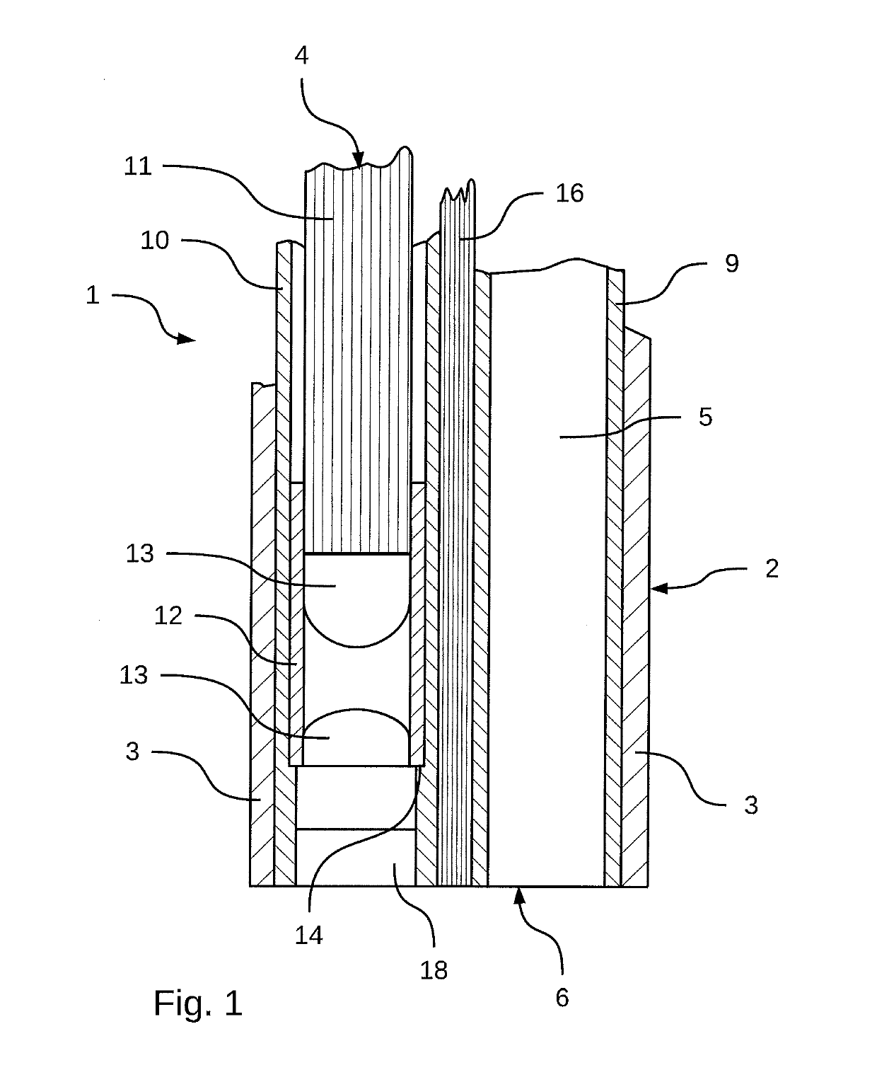
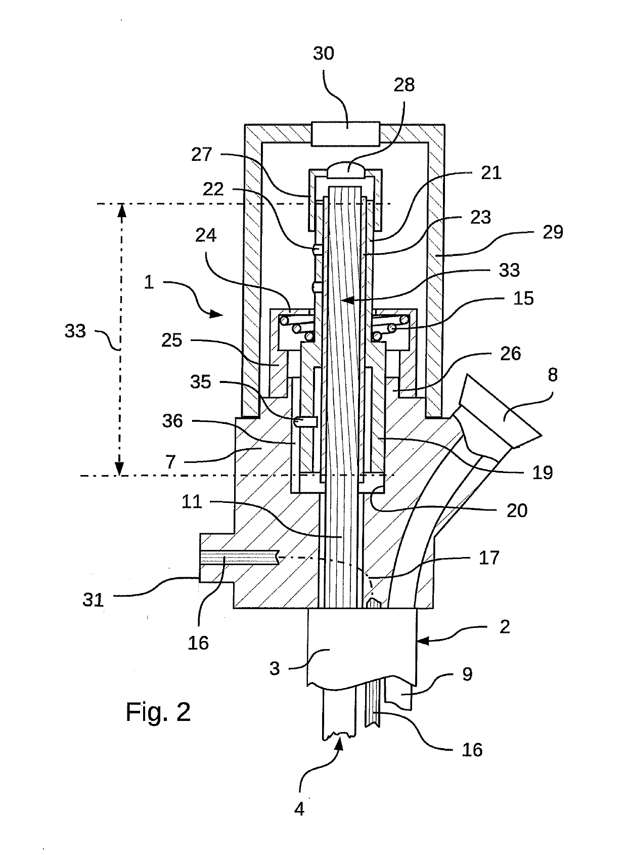
[0016]FIGS. 1 and 2 illustrate, in longitudinal section, the two end regions of an endoscope 1, which is illustrated in the exemplary embodiment as a ureteroscope.

[0017]The illustrated endoscope 1 has an elongate shaft 2, which is formed from an outer shaft tube 3, in which an image guide 4 and a working channel 5 are arranged, which both extend from their distal end in an end face 6 of the shaft 2 into a main body 7 of the endoscope 1 adjoining the proximal end of the shaft 2. In this case, the image guide 4 passes through the main body 7 in a straight path, while the working channel 5 runs angled there to a diagonal side entrance 8 of the working channel 5.

[0018]Within the shaft tube 3, the working channel 5 is surrounded by a channel tube 9. In the illustrated embodiment, the image guide 4 runs over the entire length into a guide tube 10. A substantial component of the image guide 4 is a fiber image guide 11, which is held at its distal end in a lens tube 12 which carries the obj...


PUM


Abstract

A rigid endoscope including: a shaft; a body disposed at a proximal end of the shaft, a fiber image guide mounted to move longitudinally within the shaft and body; a securing section for securing the fiber image guide, the securing section being positioned within the body; a sliding element mounted to move longitudinally within the body; and a protective sheath encasing the fiber image guide; wherein the fiber image guide is twisted, for image rotation, in a longitudinal portion corresponding to the protective sheath.

Description

CROSS-REFERENCE TO RELATED APPLICATION[0001]The present application is based upon and claims the benefit of priority from PCT / EP2017 / 063335 filed on Jun. 1, 2017, which claims benefit to DE 10 2016 006903.1 filed on Jun. 8, 2016, the entire contents of each of which are incorporated herein by reference.BACKGROUNDField[0002]The present application relates generally to rigid endoscopes, and more specifically to rigid endoscopes having fiber image guides.Prior Art[0003]An endoscope is known from DE 10 2004 009 219 A1.[0004]Rigid endoscopes have a rigid shaft tube, which can be elastically bent to various extents depending on diameter and length. They can therefore be equipped with rod lens optics, for which they are suitable due to their low flexibility.[0005]However, generic rigid endoscopes with fiber image guides find application when very thin shafts are used, which have improved flexibility and in which rod lenses would be at risk of breakage. Such generic endoscopes can be uteros...

Claims


Application Information

Patent Timeline
Patent Type & Authority Applications(United States)
IPC IPC(8): A61B1/00
CPCA61B1/00126A61B1/00167A61B1/00195A61B1/00154A61B1/018
Inventor KIEDROWSKI, GREGOR
Owner OLYMPUS WINTER & IBE
Why Eureka
Eureka Blog
Learn More