Dynamic Lighting Method and Device

a lighting method and a technology of dynamic lighting, applied in the field of lighting, can solve the problems of affecting visual health, user fatigue of human, and not making frequent dimming operations actively to the lighting equipment of users, and achieve the effect of good vision health

Active Publication Date: 2019-05-30
GUANGZHOU WLIGHT EYE TECH CO LTD
View PDF3 Cites 3 Cited by
  • Summary
  • Abstract
  • Description
  • Claims
  • Application Information

AI Technical Summary

Benefits of technology

[0084]The embodiments of the present invention provide the method of dynamic lighting, which may automatically and dynamically change and control the electrical parameters for lighting of lighting parts, in order that the dynamic lighting device output dynamic variable light, and the light is incident into the eyes of the user, and then the physiological structures of the eyes change with change of the light accordingly, thus it may overcome the defect that the user easily feels visual fatigue because of the long-term use of the eyes and it is guaranteed that the user have good vision health.

Problems solved by technology

Vision health has been a common concerned important problem to all people.
Although the lighting equipment is adjustable, it is only allowable to make dimming control under a human operation to change luminous intensity, color temperature, etc.
However, users usually would not make frequent dimming operation actively to the lighting equipment when using it.
However, when the lighting parameter is single, eye structure of human eye, which includes pupil, ciliary muscle and lens, is stayed in one state for a long time, and that causes visual fatigue of human eye thereby it affects visual health.

Method used


Image

  • Dynamic Lighting Method and Device
  • Dynamic Lighting Method and Device
  • Dynamic Lighting Method and Device

Examples


embodiment 1

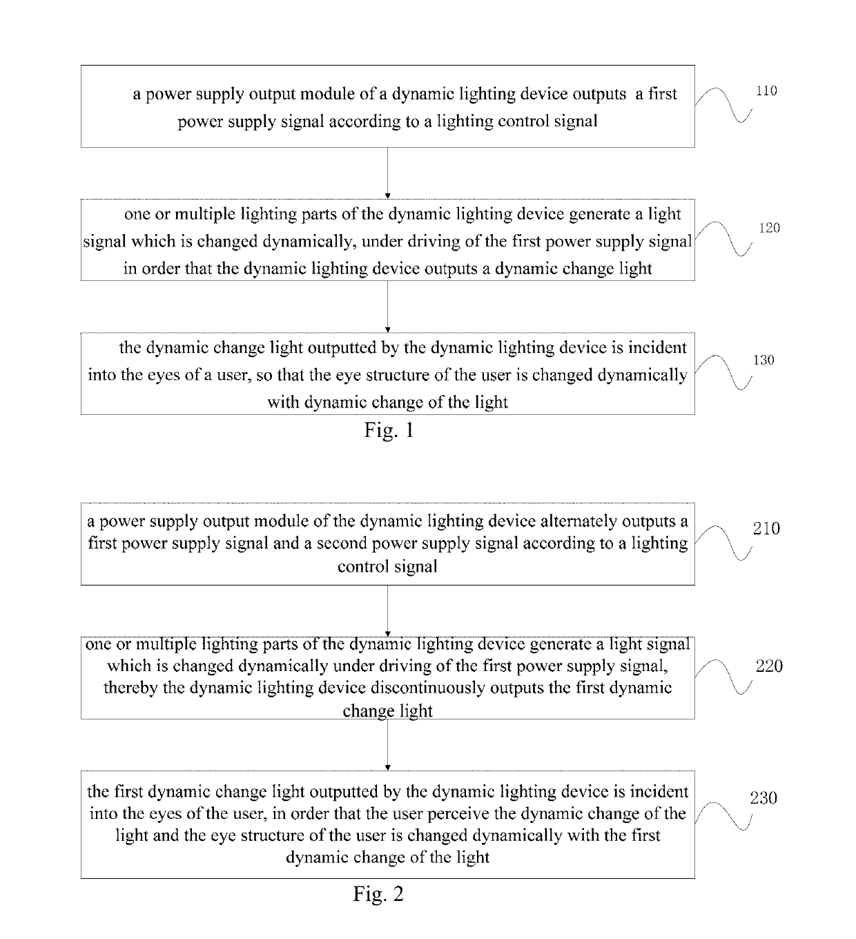
[0096]FIG. 1 is a flow chart of a dynamic lighting method provided by As shown in FIG. 1, the dynamic lighting method includes the following steps.

[0097]Step 110, a power supply output module of a dynamic lighting device outputs a first power supply signal according to a lighting control signal.

[0098]The power supply output module of the dynamic lighting device is a module used to provide power a supply driving signal for a lighting part. The power supply driving signal is determined as the first power supply signal, and the electric parameter of the first power supply signal include one or multiple groups of electrical parameters which are changed dynamically. In the case of multiple groups of electrical parameters, the multiple groups of electrical parameters are outputted in multi-channels.

[0099]The electrical parameters may be current and voltage specifically, which include the voltage value and change rate of the voltage, the current magnitude and change rate of the current, a...

embodiment 2

[0127]FIG. 2 is a flow chart of a light of dynamic illuminationing method provided by As shown in FIG. 2, the dynamically changing lighting method includes the following steps:

[0128]Step 210, a power supply output module of the dynamic lighting device alternately outputs a first power supply signal and a second power supply signal according to a lighting control signal.

[0129]Specifically, the power supply output module of the dynamic lighting device is a module used to provide power supply driving signal for a lighting part. The power supply driving signal includes a first power supply signal and a second power supply signal, and these two types of power supply signal are outputted in alternation. The alternation may be regular or irregular or random. The electric parameters of the first power supply signal include one or multiple groups of first electrical parameters which is changed dynamically, and the electric parameters of the second power supply signal include one or multiple...

embodiment 3

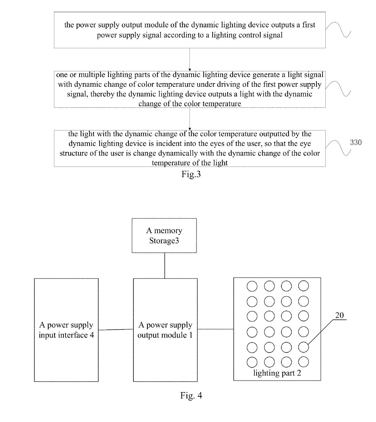
[0165]FIG. 3 is a flow chart of a dynamic lighting method provided by As shown in FIG. 3, the dynamic lighting method includes:

[0166]Step 310, the power supply output module of the dynamic lighting device outputs a first power supply signal according to a lighting control signal.

[0167]Further, the power supply output module of the dynamic lighting device is a module used to provide a power supply driving signal for a lighting part. the power supply driving signal is defined as the first power supply signal, and the electric parameters of the first power supply signal include one or multiple groups of dynamically changed electrical parameters. In the case of multiple groups of electrical parameters, the multiple groups of electrical parameters are outputted in multi-channels.

[0168]The electrical parameters may be a current and a voltage, which include the voltage value and change rate of the voltage, the current magnitude and change rate of the current, and so on. The electrical par...


PUM


Abstract

Disclosed is a dynamic lighting method, which includes a power supply output module of a dynamic lighting device outputs a first power supply signal according to a lighting control signal, electric parameters of the first power supply signal include one or more groups of dynamically changed electrical parameters, one or multiple lighting parts of the dynamic lighting device generate a dynamically changed light signal under driving of the first power supply signal, so that the dynamic lighting device outputs a light of dynamic illumination, a change rate of illumination of the light is not more than 0.02 during any time period of 0.1 second, and a ratio of the minimum and maximum values of the illumination of the light outputted by the dynamic lighting device is not more than 50%. The lighting method will result that the physiological structures of the eyes change with change of the light accordingly to overcome the defect that the user easily feels visual fatigue.

Description

[0001]This application claims priorities from Chinese patent application of No. 201610615641.7, entitled a dynamic lighting method, No. 201610617037.8, entitled a dynamically changing Lighting Method, No. 201610615656.3, entitled a dynamic lighting method with dynamic change of color temperature, No. 201610609592.6, entitled a dynamic lighting device, filed on Jul. 28, 2016, in National Intellectual Property Administration, PRC.TECHNICAL FIELD[0002]The present invention relates to the technical field of lighting, in particular to a dynamic lighting method and device.RELATED ART[0003]Vision health has been a common concerned important problem to all people. According to the study of The Report of Vision Health of Chinese reported by the Center of Health Development Research in China, of Peking university, reported on June, 2015, the people over 5 years old who are of myopia and hyperopia are mostly students and office workers in China, in 2012. The number of people of myopia or hyper...

Claims


Application Information

Patent Timeline
Patent Type & Authority Applications(United States)
IPC IPC(8): H05B33/08H05B44/00
CPCH05B33/0815H05B33/0854H05B33/0863H05B37/0272F21Y2105/12F21Y2115/10F21Y2113/13H05B45/20H05B47/19H05B47/17H05B45/10H05B47/10
Inventor CHEN, ZIPINGCHEN, MENGZHENHUANG, LEI
Owner GUANGZHOU WLIGHT EYE TECH CO LTD
Why Eureka
Try Eureka