In-vehicle radar detection system

a detection system and vehicle technology, applied in the field of vehicle radar applications, can solve the problems of increasing not only the overall cost of the resulting blind spot detection system, giving false alarms or failing to perform detection, and dead spaces between adjacent detection areas, so as to improve the overall detection range, reduce costs, and solve the effect of effective solution

Inactive Publication Date: 2019-12-05
CUBTEK INC
View PDF19 Cites 2 Cited by
  • Summary
  • Abstract
  • Description
  • Claims
  • Application Information

AI Technical Summary

Benefits of technology

[0011]Moreover, the disclosed in-vehicle radar detection system can effectively enhance its overall detection range using only two radar module. As compared to the existing system...

Problems solved by technology

However, image detection is weather-sensitive and may thus give false alarms or fail to perform detection.
However, the overlap is so narrow that dead spaces tend to exist between the adjacent detection areas.
In such a case, when an obstacle exists in such a dead space, no warning will be given because no radar apparatus can detect it.
However, use of additional radar devices increases not only the overall costs of the resulting blind-spot detection syst...

Method used


Image

  • In-vehicle radar detection system
  • In-vehicle radar detection system
  • In-vehicle radar detection system

Examples


Embodiment Construction

[0016]The following preferred embodiments when read with the accompanying drawings are made to clearly exhibit the above-mentioned and other technical contents, features and effects of the present invention. Through the exposition by means of the specific embodiments, people would further understand the technical means and effects the present invention adopts to achieve the above-indicated objectives. However, the accompanying drawings are intended for reference and illustration, but not to limit the present invention and are not made to scale.

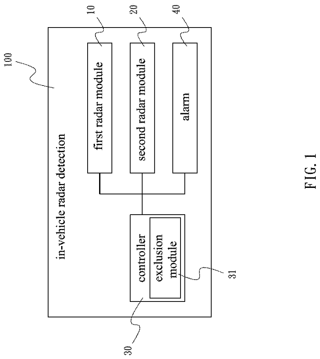
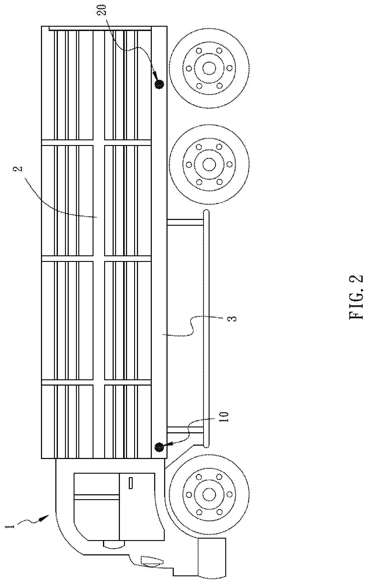
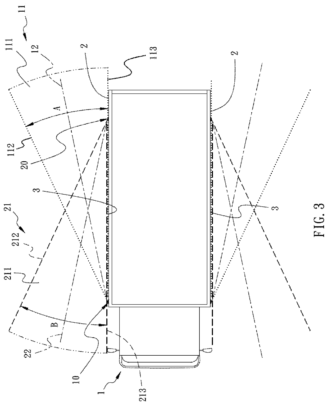
[0017]Referring to FIG. 1 through FIG. 4, the present invention provides an in-vehicle radar detection system 100, which comprises: a first radar module 10, a second radar module 20, a controller 30, and an alarm 40. The first radar module 10 and the second radar module 20 are mounted separately at the same lateral 2 or the opposite laterals 2 of the vehicle 1. In the present embodiment, the first radar module 10 and the second radar module 20...


PUM


Abstract

An in-vehicle radar detection system includes a first radar module and a second radar module separately mounted on a lateral of a vehicle. The first radar module gives a first radar signal that defines a first detection range. The second radar module gives a second radar signal that defines a second detection range. The first radar module and the second radar module give a first radar signal and a second radar signal toward each other, respectively, so that the first detection range and the second detection range fully cover the lateral of the vehicle, thereby providing full detection without any dead spaces.

Description

BACKGROUND OF THE INVENTION1. Technical Field[0001]The present invention relates to in-vehicle radar applications, and more particularly to an in-vehicle radar detection system with improved dead-space detection.2. Description of Related Art[0002]Blind-spot detection systems represent a modern type of automotive safety functionality that uses sensors mounted on a vehicle to detect whether there is an obstacle in any blind-spot area around the vehicle. In the event that a positive result is confirmed by the system, warning light or warning sound is given to inform the car driver of this, so that the driver can timely stop the car or avoid the obstacle, thereby preventing accidents that might otherwise be raised from the driver's negligence or obstructed line of sight.[0003]The existing blind-spot detection systems are most image-based and / or radar-based. Image detection relies on video cameras that take images around the relevant car and uses the resulting image signals to determine ...

Claims


Application Information

Patent Timeline
IPC IPC(8): G01S13/93G01S13/04G01S13/931
CPCG01S2013/9385G01S13/931G01S2013/9332G01S13/04G01S2013/93274G01S2013/9315
Inventor YU, SAN-CHUANCHUNG, SHYH-JONGHU, YU-WANGWANG, WEN-CHENGCHEN, HONG-LUN
Owner CUBTEK INC
Why Eureka
Try Eureka