Light source device and projector

Active Publication Date: 2019-12-26
SEIKO EPSON CORP
View PDF0 Cites 4 Cited by
  • Summary
  • Abstract
  • Description
  • Claims
  • Application Information

AI Technical Summary

Problems solved by technology

In contrast, in the case of, for example, increasing the reflectance of the combining mirror for the red laser beam, an amount of the red component included in the fluorescence and reflected by the combining mirror increases, and thus, the light loss caused in the fluorescence increases.
In the light source device described abov

Method used


Image

  • Light source device and projector
  • Light source device and projector
  • Light source device and projector

Examples


Embodiment Construction

[0016]Hereinafter, an embodiment of the present disclosure will be described with reference to the drawings.

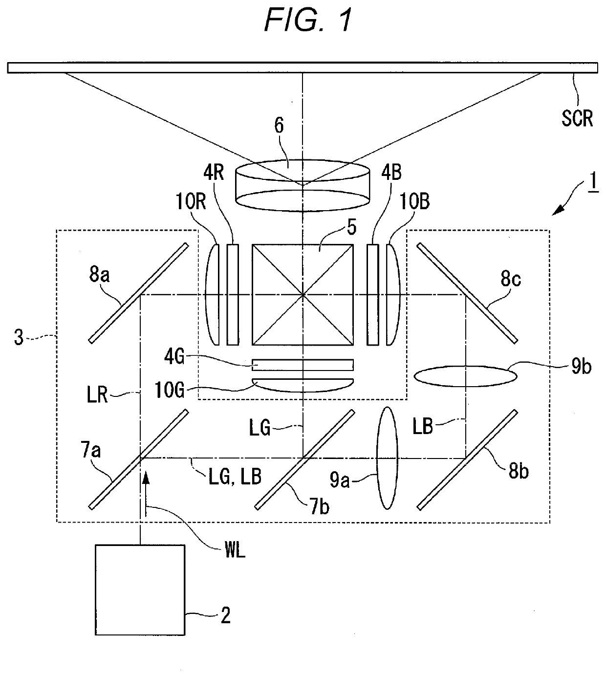
[0017]FIG. 1 is a schematic configuration diagram of a projector according to the present embodiment.

[0018]As shown in FIG. 1, the projector 1 according to the present embodiment is a projection-type image display device for displaying a color image on a screen SCR. The projector 1 is provided with a light source device 2, a color separation optical system 3, a light modulation device 4R, a light modulation device 4G, a light modulation device 4B, a combining optical system 5, and a projection optical system 6.

[0019]The light source device 2 according to the present embodiment emits white illumination light WL toward the color separation optical system 3. The color separation optical system 3 separates the illumination light WL from the light source device 2 into red light LR (e.g., light in a wavelength band of 600 nm through 700 nm), green light LG (e.g., light in a waveleng...


PUM


Abstract

A light source device is provided with a blue laser emitting element, a red laser emitting element, a light combining element, a diffusely reflecting element, a phosphor, a polarization splitting/combining element having a polarization split function, and a first wave plate. The polarization splitting/combining element guides a blue first polarization component obtained by performing polarization split on the light from the blue laser emitting element, and the light from the red laser emitting element to the diffusely reflecting element, and guides a blue second polarization component obtained by performing polarization split on the light from the blue laser emitting element to the phosphor. Then, the polarization splitting/combining element emits red diffused light, blue diffused light, a red polarization split component, and a principal fluorescence component obtained by removing the first red fluorescence component from fluorescence in one direction to thereby generate illumination light.

Description

[0001]The present application is based on, and claims priority from JP Application Serial Number 2018-116909, filed Jun. 20, 2018, the disclosure of which is hereby incorporated by reference herein in its entirety.[0002]BACKGROUND1. Technical Field[0003]The present disclosure relates to a light source device and a projector.2. Related Art[0004]In recent years, there is a technology of generating illumination light by combining a blue laser beam and fluorescence generated by excitation with the blue laser beam with each other as a light source device used for a projector. For example, in JP-A-2016-224304, there is disclosed a light source device which generates the illumination light by combining yellow fluorescence and a blue laser beam with each other, and assists a red component insufficient in the illumination light with a red laser beam.[0005]In the light source device described above, the fluorescence is transmitted through a combining mirror and the red laser beam is reflected...

Claims


Application Information

Patent Timeline
IPC IPC(8): G03B21/20H04N9/31
CPCH04N9/3158G03B21/2073G03B21/2033H04N9/3161H04N9/3164H04N9/3167G03B21/204G03B21/208G03B33/12
Inventor AKIYAMA, KOICHI
Owner SEIKO EPSON CORP
Why Eureka
Try Eureka