Light guide-based luminaire

a technology of luminaires and guides, applied in the field of luminaires, can solve the problems of increasing the overall cost of the luminaire, their own drawbacks, and the market penetration of such devices, and achieve the effect of facilitating its mounting and reducing the overall weight of the luminair

Inactive Publication Date: 2020-06-18
SIGNIFY HLDG BV
View PDF6 Cites 0 Cited by
  • Summary
  • Abstract
  • Description
  • Claims
  • Application Information

AI Technical Summary

Benefits of technology

[0019]In a particular set of embodiments, the luminaire is a troffer as such ceiling-mounted luminaires typically are large area luminaires that benefit from a compact design as well as from low-cost. For example, the compact nature of the luminaire according to at least some of the embodiments of the present invention allows for such a luminaire to be fitted in tight headsp...

Problems solved by technology

Nevertheless, market penetration of such SSL devices is not without challenges.
A more serious challenge is to produce a luminous output with an SSL device that produces an aesthetically pleasing luminous output distribution.
However, such solutions each have th...

Method used


Image

  • Light guide-based luminaire
  • Light guide-based luminaire
  • Light guide-based luminaire

Examples


Embodiment Construction

[0028]It should be understood that the Figures are merely schematic and are not drawn to scale. It should also be understood that the same reference numerals are used throughout the Figures to indicate the same or similar parts. It furthermore should be understood that where reference is made to a metal in the present application, this includes metal alloys unless specifically stated otherwise.

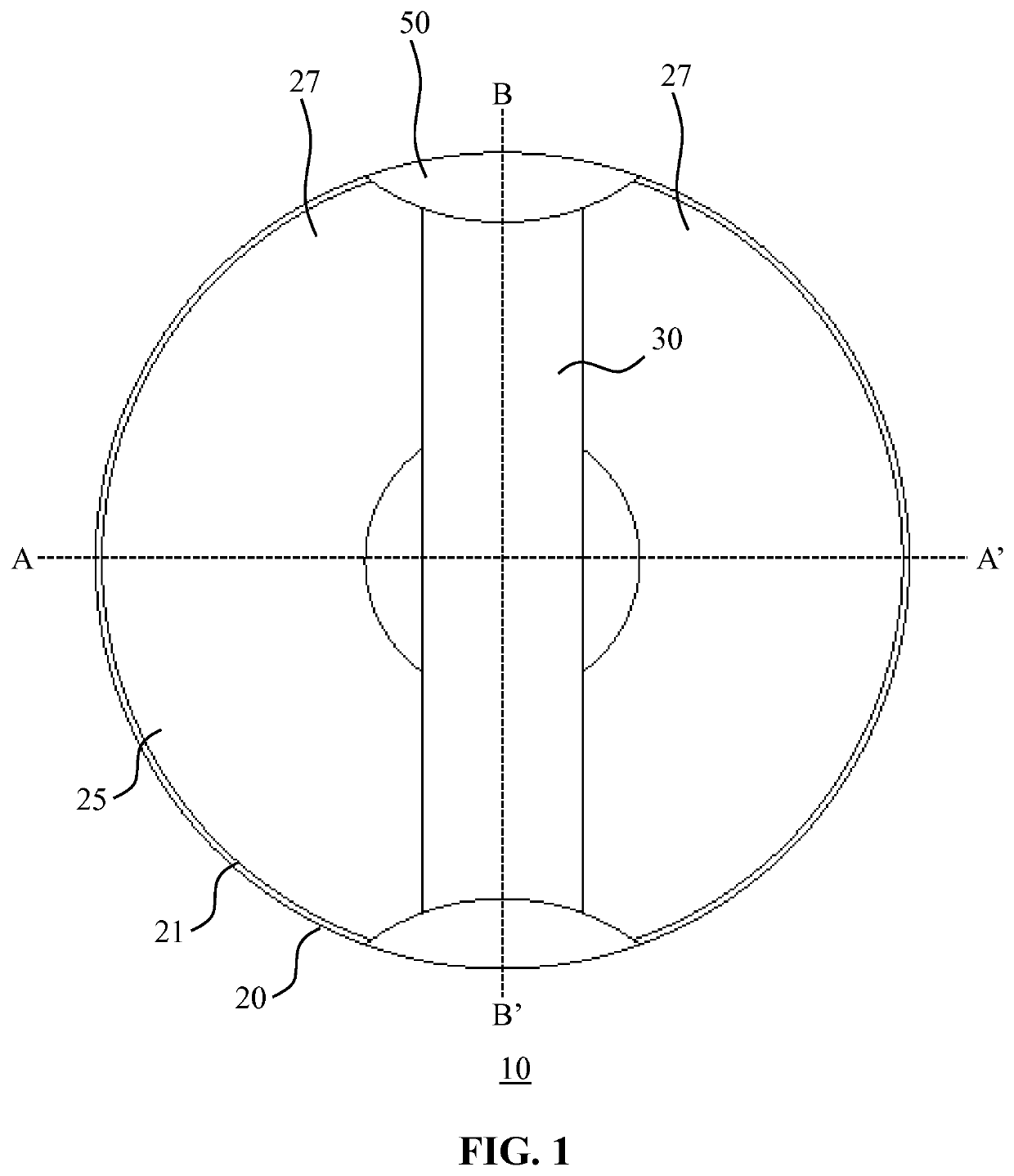
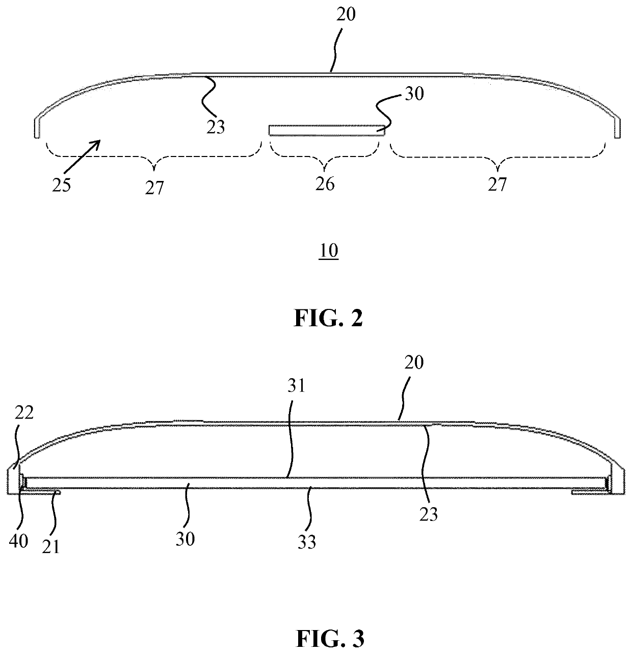
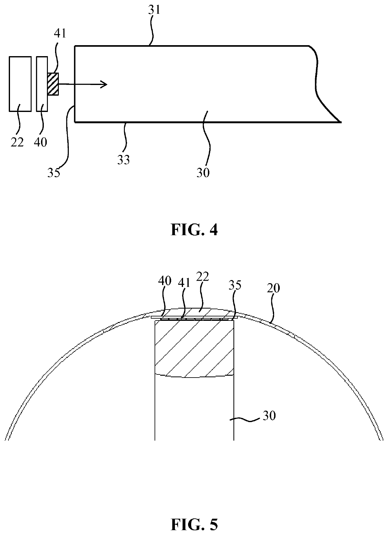
[0029]FIG. 1 schematically depicts a face-on view of a luminaire 10 according to an embodiment of the present invention, more specifically of the light exit window 25 of the luminaire 10. The light exit window 25 is delimited by an edge or rim 21 of the housing 20 of the luminaire 10. Across the light exit window 25 extends an elongate light guide 30 that is mounted in the housing 20. The light guide 30 typically covers only a part of the light exit window 25, such as a central region of the light exit window 25, with at least one region of the light exit window 25, e.g. two regions on opposit...


PUM

PropertyMeasurementUnit
Lengthaaaaaaaaaa
Heightaaaaaaaaaa
Lightaaaaaaaaaa

Abstract

A luminaire (10) is disclosed comprising a housing (20) delimiting a light exit window (25) and comprising a reflective inner surface (23) facing the light exit window, an elongate light guide (30) mounted in the housing and partially covering the light exit window by extending in an elongation direction across a central region (26) of the light exit window, the elongate light guide comprising a first major surface (31) facing the reflective inner surface, a second major surface (33) opposite the first major surface, plurality of light outcoupling structures (37) proximal to the second major surface arranged to redirect light onto the reflective inner surface through the first major surface; and a pair of opposing side surfaces (35) in said elongation direction extending between the first major surface and the second major surface. The luminaire further comprises at least one light source (41) arranged to couple light into the light guide via one of said opposing side surfaces (35).

Description

FIELD OF THE INVENTION[0001]The present invention relates to a luminaire comprising a housing delimiting a light exit window and a light guide mounted in the housing.BACKGROUND OF THE INVENTION[0002]Solid state lighting (SSL), e.g. LED lighting, is rapidly gaining popularity because of its energy credentials and superior lifetime compared to traditional lighting, e.g. incandescent lighting, fluorescent lighting and halogen lighting. Nevertheless, market penetration of such SSL devices is not without challenges. For example, purchase cost of SSL devices is still higher than that of equivalent traditional light sources, even though the effective cost of such SSL devices is markedly lower due to their much longer lifetime, and this realisation by consumers is one of the reasons for the increased popularity of SSL.[0003]A more serious challenge is to produce a luminous output with an SSL device that produces an aesthetically pleasing luminous output distribution. Most SSL devices, e.g. ...

Claims


Application Information

Patent Timeline
IPC IPC(8): F21V8/00F21S8/02F21V7/28F21V7/04
CPCG02B6/0068F21S8/026F21V7/04G02B6/0088G02B6/0055G02B6/0043F21V7/28F21V7/0008F21V7/0091G02B6/0011F21Y2105/00F21Y2115/10G02B6/0041G02B6/009
Inventor BAO, JING
Owner SIGNIFY HLDG BV
Why Eureka
Try Eureka