Color filter substrate, manufacturing method thereof, and related devices

Active Publication Date: 2020-10-01
BOE TECH GRP CO LTD +1
View PDF0 Cites 0 Cited by
  • Summary
  • Abstract
  • Description
  • Claims
  • Application Information

AI Technical Summary

Benefits of technology

[0028]According to an embodiment of the present disclosure, in the color filter substrate as proposed above, the first distance between the upper surface of the transparent layer 03 corresponding to the color resist units m of different colors and the upper surface of the base plate 01 is different, as shown in FIG. 1. This means that if the color resist units m of different colors have a same thickness, as shown in FIG. 1, different portions of the transparent layer corresponding to the color resist units m of different colors will have different thicknesses. For instance, in FIG. 1, color resist units of R, G, and B colors are taken as an example. In this case, portions of the transparent layer corresponding respectively to the color resist units m of R, G, and B colors obviously have different thicknesses. In this way, when the color filter substrate is applied to a liquid crystal display panel, the color resist units of different colors will correspond to different cell thicknesses, because typically a distance between the array substrate and the color filter substrate will be constant in the liquid crystal display panel. I.e., it remains the same across the entire display panel. In particular, different cell thicknesses corresponding to color resist units of different colors can be respectively selected such that light of a corresponding color is emitted out from the display panel at the maximum transmittance. Thereby, when white light or natural light is incident on the liquid crystal display panel, the transmittance of the entire liquid crystal display panel is maximized, because light of each and every color has the maximum transmittance. This helps to facilitate the realization of transparent display with high transmittance.

Problems solved by technology

Therefore, how to improve the transmittance of a display panel to realize transparent display is an urgent technical problem to be solved by those skilled in the art.

Method used


Image

  • Color filter substrate, manufacturing method thereof, and related devices
  • Color filter substrate, manufacturing method thereof, and related devices
  • Color filter substrate, manufacturing method thereof, and related devices

Examples


Embodiment Construction

[0025]Specific embodiments of the color filter substrate, the manufacture method thereof and the related devices according to embodiments of the present disclosure will be explained below in detail with reference to the drawings.

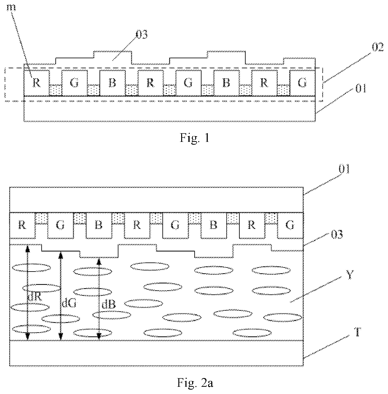
[0026]According to an embodiment of the present disclosure, a color filter substrate is provided. As shown in FIG. 1, the color filter substrate can comprise a base plate 01 and a color filter layer 02 located on the base plate 01. Specifically, the color filter layer 02 comprises multiple rows of color resist units m, wherein color resist units in each row have at least three different colors. Furthermore, the color filter substrate can further comprise a transparent layer 03, wherein the transparent layer 03 is arranged on a side of the color filter layer 02 away from the base plate 01, and in particular covers the color filter layer 02. Referring to FIG. 1, in the color filter substrate, a first distance between a surface of the base plate 01 close to the...


PUM

PropertyMeasurementUnit
thicknessaaaaaaaaaa
thicknessesaaaaaaaaaa

Abstract

A color filter substrate, a manufacturing method thereof, and related devices. The color filter substrate includes: a base plate; a color filter layer on the base plate; and a transparent layer on a side of the color filter layer away from the base plate. Specifically, the color filter layer includes multiple rows of color resist units, wherein color resist units in each row have at least three different colors. In addition, a first distance between a surface of the base plate close to the color resist units and a surface of the transparent layer away from the color resist units may be different for color resist units of different colors.

Description

[0001]The present application is the U.S. national phase entry of PCT / CN2017 / 108020 filed on Oct. 27, 2017, which claims the priority of the Chinese patent application No. 201710232616.5 filed on Apr. 11, 2017, the entire disclosures of which are incorporated herein by reference.TECHNICAL FIELD[0002]The present disclosure relates to the field of display technologies, and in particular to a color filter substrate, a manufacturing method thereof, and related devices.BACKGROUND ART[0003]Nowadays, display technologies have been widely applied in televisions, cellphones and display of public information. Flat displays for image display are popularized for being ultra-thin and energy-saving, and have permeated into every aspect of people's life. In particular, more and more display products have begun to use transparent display techniques. Transparent display products boast advantages such as a light weight and thinness, portability, supportability of 3D display, and a higher user experie...

Claims


Application Information

Patent Timeline
Patent Type & Authority Applications(United States)
IPC IPC(8): G02F1/1335
CPCG02F2201/52G02F1/13394G02F1/133371G02F2201/50G02F1/133516G09G2300/0452G02F1/133514G02F2001/133519G02F1/133519
Inventor WU, XIAOJUNZHANG, ZIJING
Owner BOE TECH GRP CO LTD
Why Eureka
Try Eureka