Tool for enlarging hole

a tool and hole technology, applied in the field of enlarging holes, can solve the problem of difficult proposition of enlarging holes

Inactive Publication Date: 2000-04-11
NEWFREY
View PDF15 Cites 22 Cited by
  • Summary
  • Abstract
  • Description
  • Claims
  • Application Information

AI Technical Summary

Problems solved by technology

Enlarging a hole is a very difficult proposition.

Method used


Image

  • Tool for enlarging hole
  • Tool for enlarging hole
  • Tool for enlarging hole

Examples


Embodiment Construction

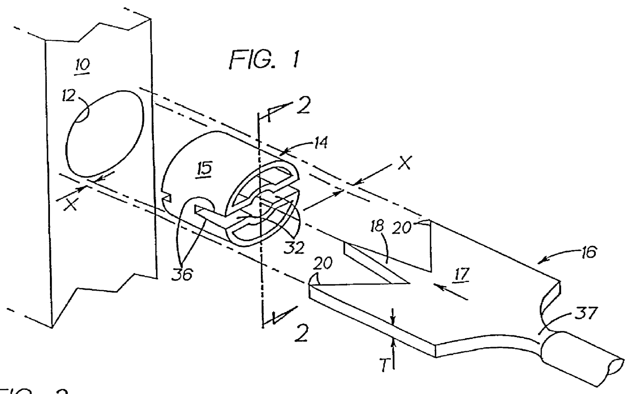
FIG. 1 shows the edge of a door 10 having a bore 12 extending horizontally thereinto for receiving the cylindrical housing of a latch assembly of a conventional lockset (not shown). This bore has a selected diameter, 7 / 8", for example. It may become desirable to change locksets and to replace the existing lockset with another lockset which has a latch assembly that has a larger cylindrical body (1", for example). It then becomes necessary to enlarge this bore from 7 / 8" to 1", for example. Alternately, it may be desirable to enlarge the cylindrical bolt receiving hole in the strike and door jamb so that a strike plate having a bigger bolt receiving hole can be used. For example, it might be desirable to enlarge bolt receiving hole in the door jamb from 1" to 1 3 / 8", for example.

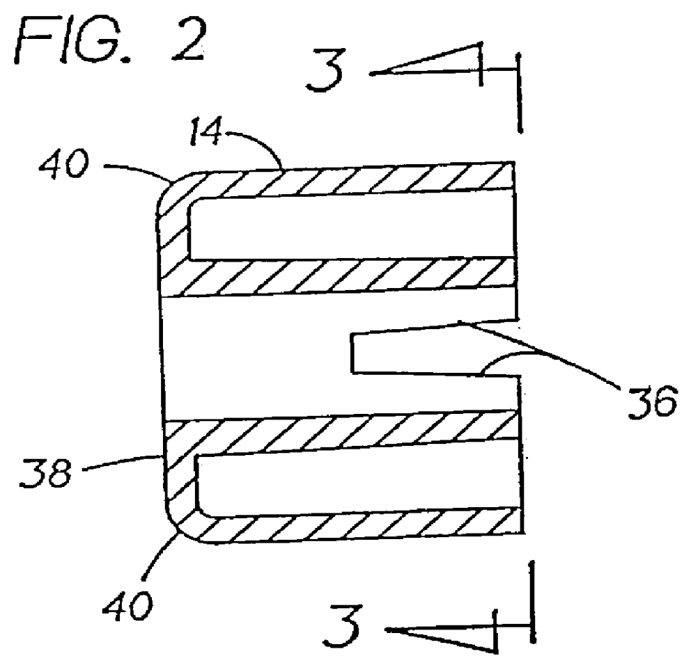
A cylindrical drilling guide 14, which may be made of plastic, has a cylindrical body 15 which has a diameter slightly smaller than the diameter of the existing bore (the guide can be slid easily into the hole...


PUM

PropertyMeasurementUnit
sizeaaaaaaaaaa
hole sizeaaaaaaaaaa
diameteraaaaaaaaaa

Abstract

A tool for enlarging the size of an existing bore to a selected enlarged size. The tool has a drill sized to define the enlarged bore, and a guide having a cylindrical body sized so that the guide can be rotated in the existing bore. The guide and drill including cooperating structures for releasably interconnecting the guide and the drill with the guide and drill coaxially aligned whereby, with the guide releasable secured to the drill, the guide can be located within the original hole to guide the cutting action of the drill as it enlarges the original hole.

Description

The present invention relates to locksets which are to be mounted on a door and more particularly to replacement locksets.A lockset conventionally includes a latch assembly which has a cylindrical bolt supporting body insertable into a cylindrical bore drilled into the edge of the door. Replacement locksets may include a latch assembly which has a larger cylindrical bolt supporting body which is too big to be inserted into the original cylindrical hole. It may also be desirable to enlarge the strike hole in the door jamb. Enlarging a hole is a very difficult proposition.It is known from U.S. Pat. No. 5,366,326, to snugly fit a hole saw guide into a through hole to be enlarged. This guide has a concentric hole which serves as a bearing surface for the pilot drill of a hole saw as the hole saw is brought into cooperation with the guide to enlarge the hole. The guide is tapered so that this snug fit can be achieved with small variations in hole size.It is accordingly an object of the p...

Claims


Application Information

Patent Timeline
Patent Type & Authority Patents(United States)
IPC IPC(8): B23B51/04B23B51/00B27G15/00B27F5/12B27F5/00
CPCB23B51/0054B23B51/0426B27F5/12B27G15/00Y10T408/902Y10T408/5584Y10T408/8923Y10T408/96B23B51/0018B23B51/00035
Inventor FREEMAN, GLENN D.
Owner NEWFREY
Why Eureka
Try Eureka