Torque converter

a torque converter and converter output shaft technology, applied in the direction of rotary clutches, fluid couplings, gearings, etc., can solve the problems of achieving the limit, affecting the output shaft of the converter, and unable to damped vibrations to the desired exten

Inactive Publication Date: 2000-06-06
ZF FRIEDRICHSHAFEN AG
View PDF3 Cites 24 Cited by
  • Summary
  • Abstract
  • Description
  • Claims
  • Application Information

AI Technical Summary

Problems solved by technology

Thus, when the torsional vibration damper is designed too rigid, these occurring vibrations cannot be damped to the desired extent.
However, in the non-bypassed state in which torque conversion occurs, a relatively large torque is transmitted to the converter output shaft by the turbine wheel.
This torque must be transmitted through the torsional vibration damper, so that if the torsional vibration damper is designed too soft, it very quickly reaches its limit and can accordingly no longer provide a damping function.
As a result, the desired decoupling of vibrations cannot be provided by the torsional vibration damper in the case of smaller transmitted torques or smaller torque variations.

Method used


Image

  • Torque converter
  • Torque converter
  • Torque converter

Examples


Embodiment Construction

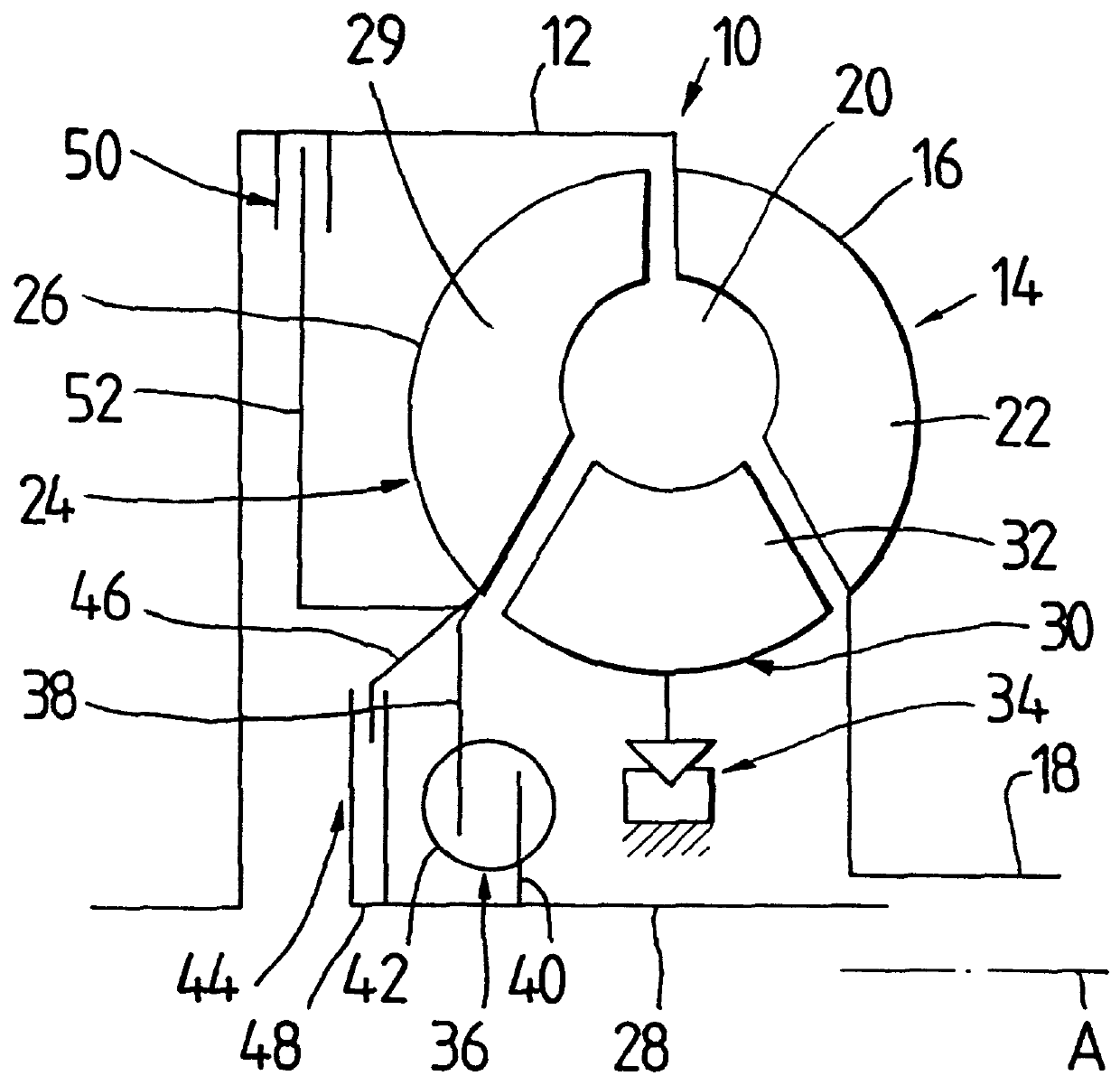
FIG. 1 is a schematic view of a torque converter 10 according to the invention. The converter 10 comprises a housing 12 which carries an impeller wheel generally designated by 14. The impeller wheel 4 is substantially formed by an impeller wheel shell 16 and an impeller wheel hub 18 connected with the impeller wheel shell 16 at the radial inside so as to be fixed against rotation relative to it. In a known manner, the impeller wheel hub 18 drives a fluid pump by which a work fluid can be delivered to the interior 20 of the torque converter 10. Further, the impeller wheel shell 16 has a plurality of impeller vanes 22 by which the work fluid contained in the interior 20 of the converter is conveyed in the direction of a turbine wheel 24 which is likewise arranged in the interior of the converter. The turbine wheel 24 also has a turbine wheel shell 26 which is coupled with a turbine wheel hub 28 in the manner described hereinafter. The turbine wheel 24 likewise has a plurality of turbi...


PUM


Abstract

A torque converter having a converter housing which is coupled to a driving unit, a turbine wheel which is arranged in the converter housing and is rotatable with respect to the converter housing about an axis of rotation and has a turbine wheel shell and a turbine wheel hub which is connected with the turbine wheel shell and which can be coupled with or is coupled with a converter driven shaft. A lockup clutch provides selectable rotational coupling of the converter housing with the turbine wheel, and a torsional vibration damper arrangement is provided in the power transmission path between the converter housing and the turbine wheel hub and/or between the turbine wheel shell and the turbine wheel hub. A friction device is connected parallel to the torsional vibration damper arrangement in the power transmission path for generating a frictional force which may be changed in a selected manner.

Description

1. Field of the InventionThe present invention relates to torque converters and more particularly to a torque converter having increased vibration damping characteristics in many different operating states.2. Description of the Related ArtA torque converter is known from DE 195 14 411 A1, wherein a torsional vibration damper is arranged in the connection path between the turbine wheel shell and the turbine wheel hub. A toothing at the shell engages with a counter-toothing at the hub, and provides a rotational play which limits the rotational angle for the torsional vibration damper formed by the engagement of the teeth with one another. Further, a lockup clutch is provided which, in order to transmit power, is coupled to the side of the torsional vibration damper that is also coupled with the turbine wheel shell. That is, the torsional vibration damper is active when the lockup clutch is in its disengaged state and the turbine wheel is rotatably driven during converter operation by ...

Claims


Application Information

Patent Timeline
Patent Type & Authority Patents(United States)
IPC IPC(8): F16H45/00F16H45/02
CPCF16H45/02F16H2045/0278F16H2045/0247F16H2045/007
Inventor SASSE, CHRISTOPH
Owner ZF FRIEDRICHSHAFEN AG
Why Eureka
Try Eureka