Device for controlling a position indicator on a visual display

a technology of visual display and position indicator, which is applied in the direction of instruments, computing, electric digital data processing, etc., can solve the problems of reducing the height of the control device and the height dimension of the control device only, and restricting the minimum height dimension of the control device, so as to achieve the effect of reducing the overall height of the mouse, easy miniaturization, and simple construction

Inactive Publication Date: 2000-07-25
BLACKBERRY LTD
View PDF16 Cites 42 Cited by
  • Summary
  • Abstract
  • Description
  • Claims
  • Application Information

AI Technical Summary

Benefits of technology

As a result, the user does not have to exclusively rely on watching a cursor or pointer on a screen when operating the position indicator controlling device because of the audible or sensory indications provided, the input device is simple in construction and it may easily be miniaturized.
The position indicator controlling devices disclosed herein are especially intended for use with a laptop computer, where the indicator position controller has its exposed part-spheroidal portion protruding from an upper side of th

Problems solved by technology

However, particularly where the control device is to be used with a laptop computer, where customer demand is for reduced space requirements, in particular lower height dimensions, a reduced height both for the ov

Method used


Image

  • Device for controlling a position indicator on a visual display
  • Device for controlling a position indicator on a visual display
  • Device for controlling a position indicator on a visual display

Examples


Embodiment Construction

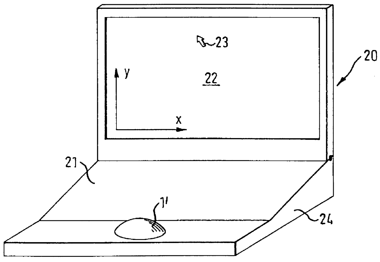
Referring to FIG. 2, there is shown a diagrammatic perspective view of a laptop computer 20 having a main body 24, a keyboard 21, a display screen 22 forming a lid for the main body, and a position indicator controlling device 1' mounted in the centre of a forward portion of the main body 24 for controlling the position of a cursor 23 on the screen so that, for example, it becomes coincident with a menu option, item of alphanumeric text, or the like for which a command is to be input to the laptop computer.

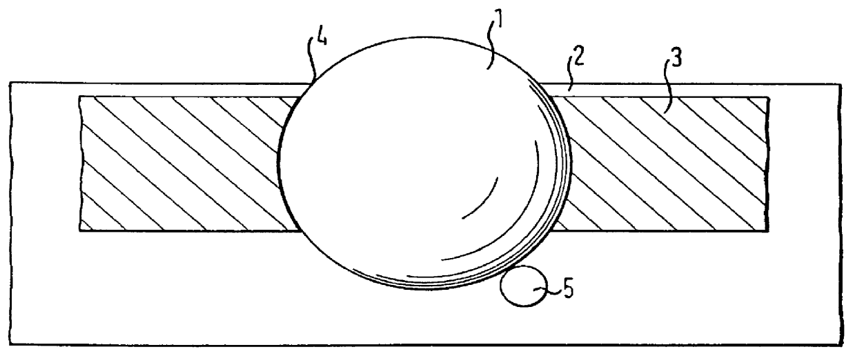
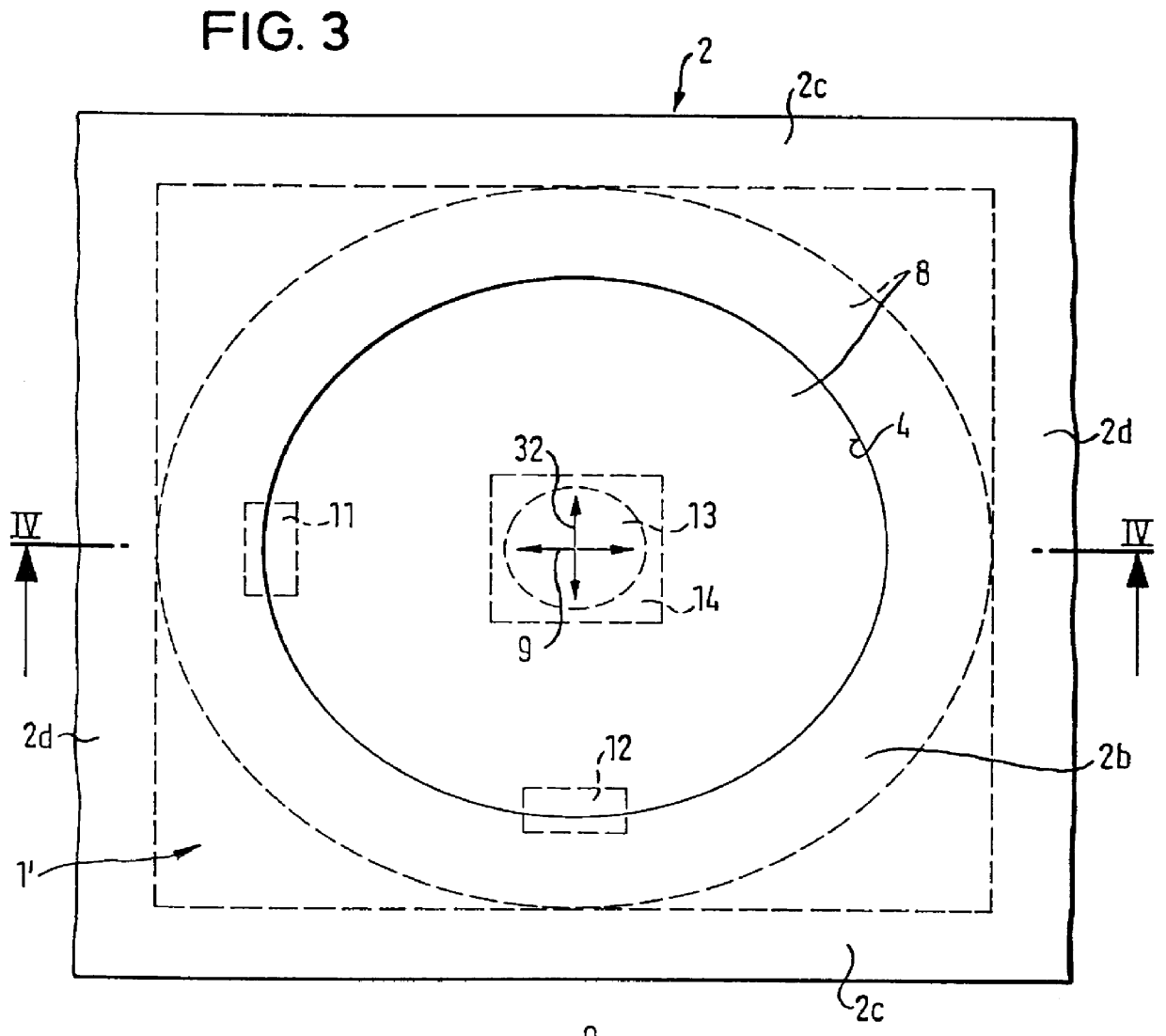
Referring now to the first embodiment shown in FIGS. 3 and 4, the construction of the position indicator controlling device 1' is shown in more detail. The device can be an integral part of the laptop computer or it can be a separate unit, secured in an appropriate manner to the laptop computer body.

In FIGS. 3 and 4, there is shown a housing 2 comprising an underside or bottom wall 2a, an upperside or top wall 2b, opposite side walls 2c and end walls 2d. The housing is of generall...


PUM


Abstract

For controlling a position indicator, e.g. a cursor, on a visual display, e.g. the monitor screen associated with a personal computer or a laptop computer screen, a position indicator controlling device (1) comprises an indicator position controller (6) in the form of a continuous membrane of elastomeric material (8) stretched, in wrinkle-free manner, around a solid form-keeping core (7) held captive in a housing (2) so that by applying finger pressure in a generally horizontal direction to an uppermost exposed, part-spheroidal, portion of the membrane, the membrane can slide on the core to produce a corresponding output signal from one or more motion detectors (11, 12). The indicator position controller gives the appearance to a user of a spherical ball device (such as is commonly used in a laptop computer), but the special shape of the form-keeping core is such as to reduce the overall height requirement and leads to a heightwise compact construction for the position indicator controlling device (1'). According to two modifications (FIGS. 5 and 6), the indicator position controller (6) is realized by a normally spheroidal thick-walled elastomeric ball (8'), or by a solid elastomeric ball (8'') held in a deformed state by the housing (2). The position indicator controlling device (1) can be designed for use as a ball-type device for a laptop computer or as a mouse for a personal computer.

Description

The present invention relates to a device for controlling a position indicator on a visual display, comprising a housing, an indicator position controller held captive in the housing so as to expose a part-spheroidal portion of the position controller for enabling a user to rotate the same substantially about the centre of curvature of the centre-most exposed region of the part-spheroidal portion, and detector means for providing output signals dependent on the rotation of the part-spheroidal portion. Such a device is well known in the art, for example a mouse for controlling the position of a cursor or indicator on a display screen of a personal computer or a ball-type device for performing the same function for a laptop computer.TECHNICAL BACKGROUND AND PRIOR ARTVarious types of devices for manually controlling a position indicator on a visual display are known, e.g. keyboards or push button arrays. With the advent of electronic devices using display screens to inform the user and...

Claims


Application Information

Patent Timeline
IPC IPC(8): G06F3/033G06F3/0338
CPCG06F3/033G06F3/0338
Inventor KODIM, WALTER
Owner BLACKBERRY LTD
Why Eureka
Try Eureka