Screen frame and screen door

a screen and frame technology, applied in the field of screen frame and screen door, can solve the problems of ineffective screen in preventing a potential intruder, human or animal, from entering the structure, ineffective screen in preventing most projectiles, and little in the way of rigidity or protection against damage by projectiles, intruders, and the elements

Inactive Publication Date: 2000-08-29
STORY JR PAUL J
View PDF26 Cites 32 Cited by
  • Summary
  • Abstract
  • Description
  • Claims
  • Application Information

AI Technical Summary

Benefits of technology

Accordingly, one of the objects of the present invention is to pro...

Problems solved by technology

However, screens are ineffective in preventing a potential intruder, human or animal, from entering the structure when the window pane or door is left open.
Also, screens are ineffective in preventing most projectiles from breaking through a screen and entering the structure.
While existing screen frames and screens are inexpensive, they offer very little in the way of rigidity or protection against damage by projectiles, intruders, and the elements.
First, such screens are constructed out of materials that have inferior characteristics compared to metal screens.
Fiberglass or nylon screening can be easily cut or torn and, therefore, offers very little resistance to a potential intruder or a projectile.
In addition, the frame segments are made from a material which can be readily destroyed and which offer little resistance to external pressure applied during forcible removal or entry through a window frame.
Finally, the frame corners where the screen frame segments are joined, are insufficiently sturdy to offer protection against damage.
Consequently, wi...

Method used


Image

  • Screen frame and screen door
  • Screen frame and screen door
  • Screen frame and screen door

Examples


Embodiment Construction

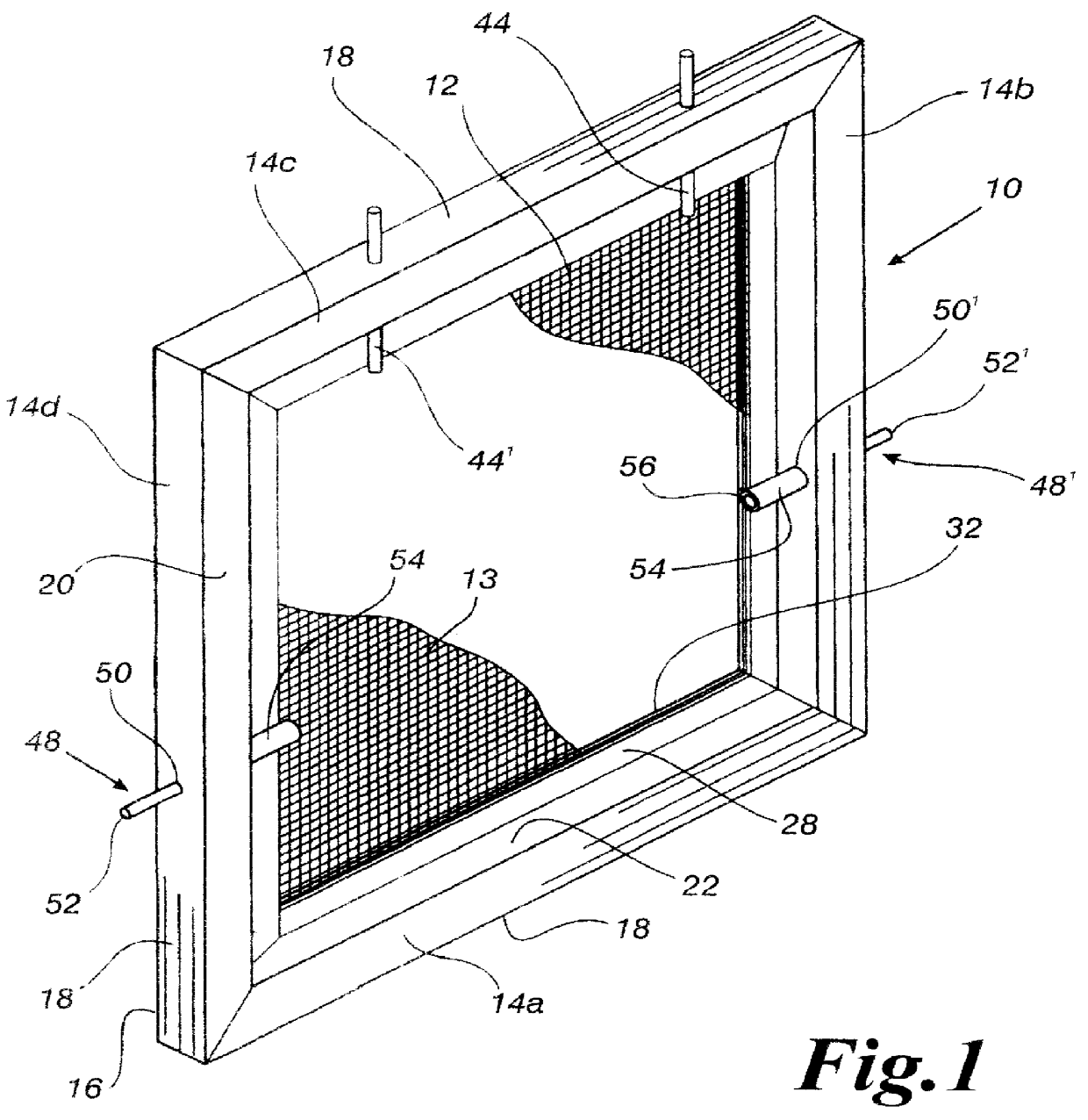
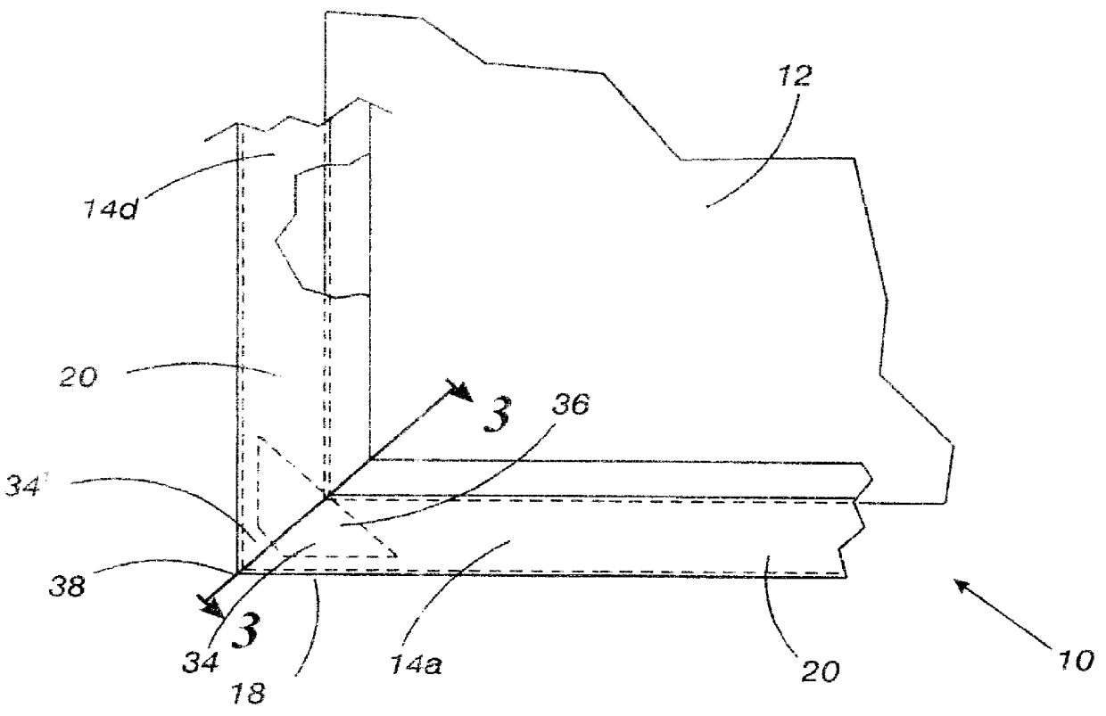
Referring now to the drawings, FIGS. 1-3 and 7-9 show a first embodiment of the invented screen frame 10 and screen 12 for screening a window or door. The invented screen frame 10 includes four screen frame segments 14a, 14b, 14c, 14d joined together at corners to form a generally rectangular shaped screen frame 10. Three screen frame segments (not shown) would be used to form a triangle screen frame enclosing a screen, and additional screen frames may be used for windows having more than four sides.

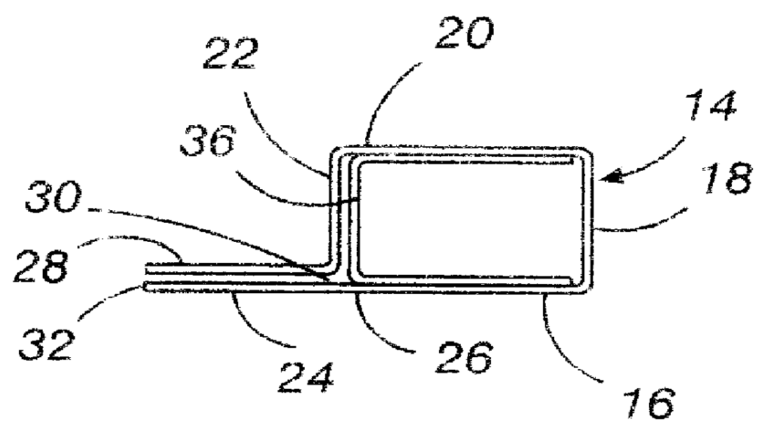
The screen frame segments 14 are preferably stainless steel extrusions having a back side 16, an outer facing, or outer perimeter side 18 extending generally perpendicular from the bottom side 16, a front facing side 20 extending generally perpendicular from the outer side 18 and generally parallel to the back side 16, and an inner side or interior perimeter 22 extending generally perpendicular from the front facing side 20 and generally parallel to the outer side 18.

As shown in FIGS. 2-...


PUM


Abstract

The present invention is a screen frame and screen positionable in most window frames and door frames. The invented screen frame is comprised of four screen frame segments joined together at corners to form a generally rectangular or multi-sided screen frame. Corner joint inserts are inserted in each corner of the four screen frame segments and the inserts are spot welded to adjoining screen frame segments to provide a sturdy and rigid screen frame. The screen frame segments are preferably stainless steel extrusions having two parallel flanges extending from a generally square shaped hollow body. An alternative construction of the screen frame is a continuous extruded segment that is notched at certain locations for bending and forming into a continuous screen frame having one junction requiring spot welding. A metal, preferably stainless steel screen is secured in the screen frame by spot welding the screen between the screen frame flanges of the screen frame segment. Stainless steel support pins are used to secure the screen frame enclosing the screen in a window frame casing. The screen frame and screen provides a long-lasting, corrosive resistant, and rigid frame and screen for positioning in window or door frames which withstand damage from intruders, projectiles, and environmental stresses.

Description

The present invention relates to window screens and screen doors. More particularly, the invention relates to a sturdy, rigid, and durable stainless steel screen frame and stainless steel screen capable of resisting damage from intruders, projectiles, and environmental stresses.Screens are often used to prevent everything except air from entering through windows when the window panes are in open positions. Screens are also used in conjunction with doors for similar reasons. Screens are effective in preventing bugs and small animals from entering a structure. However, screens are ineffective in preventing a potential intruder, human or animal, from entering the structure when the window pane or door is left open. Also, screens are ineffective in preventing most projectiles from breaking through a screen and entering the structure.Existing screens for windows and doors are typically constructed of aluminum frame segments and fiberglass, metal wire, or nylon screens. A typical screen f...

Claims


Application Information

Patent Timeline
IPC IPC(8): E06B9/52
CPCE06B9/52
Inventor STORY, JR., PAUL J.
Owner STORY JR PAUL J
Why Eureka
Try Eureka