

Compact flash card connector
- Summary
- Abstract
- Description
- Claims
- Application Information
AI Technical Summary
Benefits of technology
Problems solved by technology
Method used
Image

Examples
Embodiment Construction
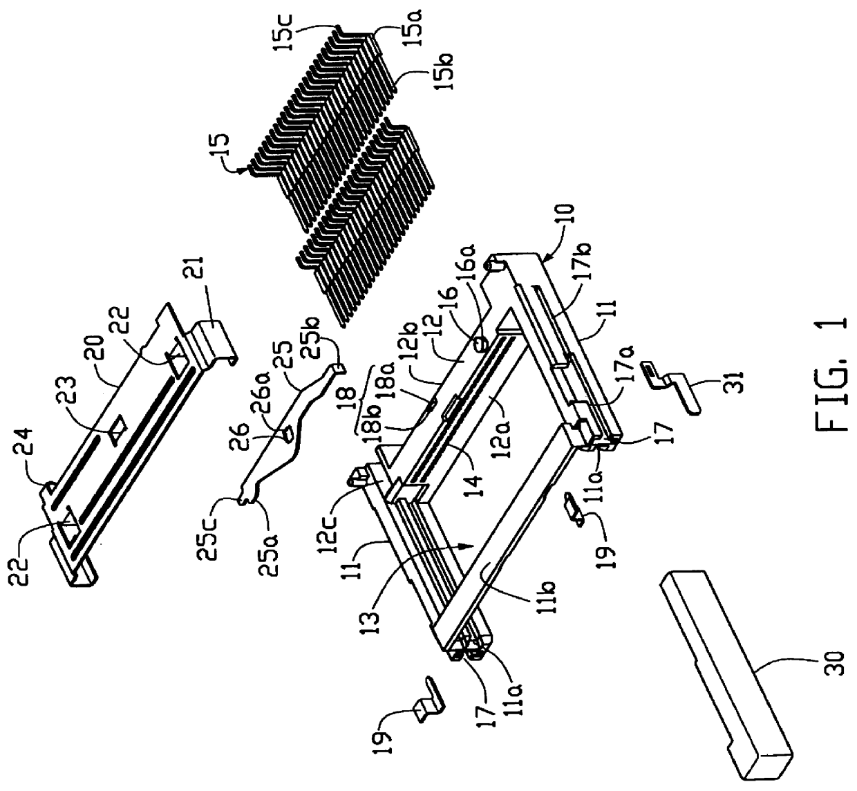
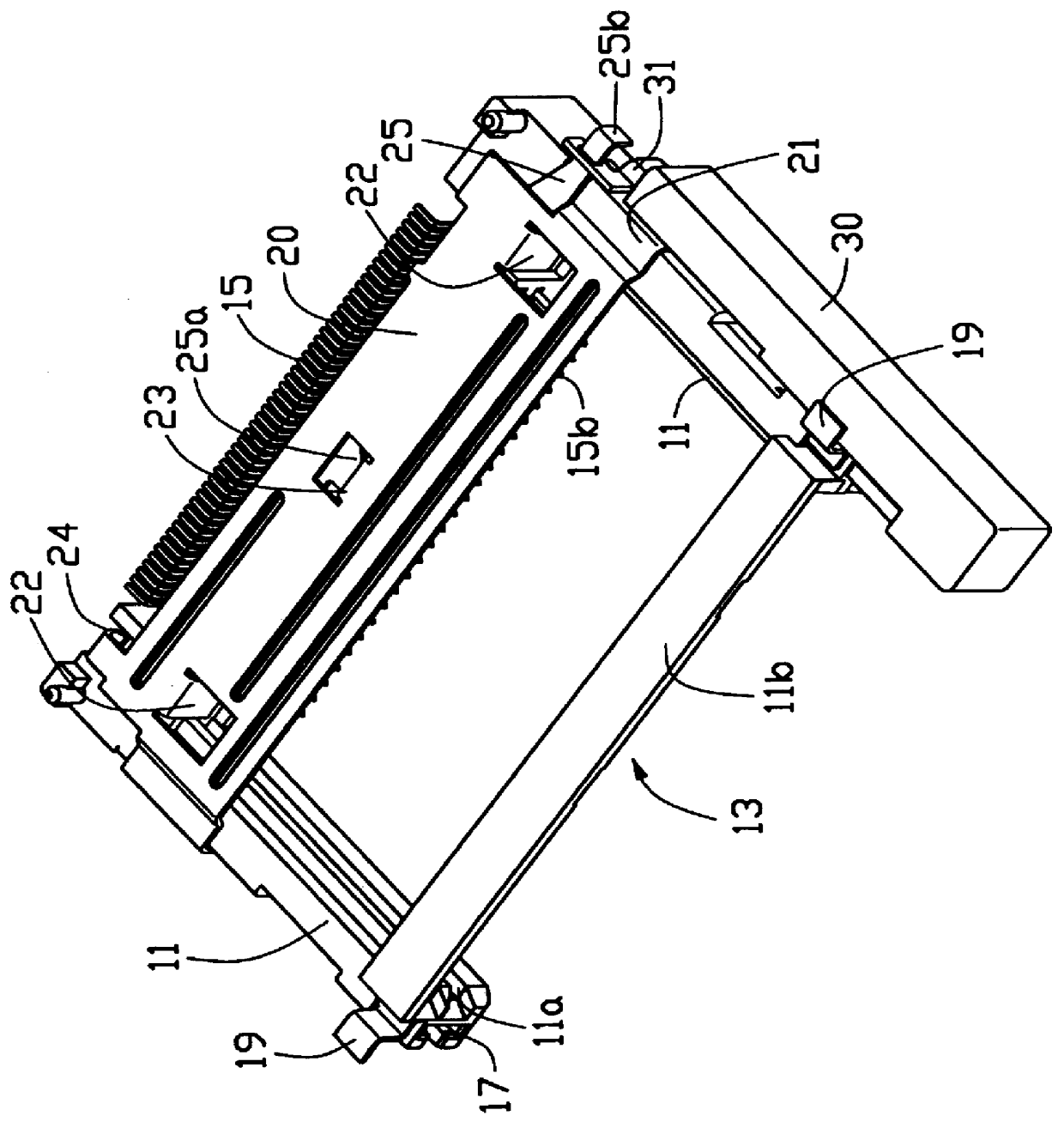
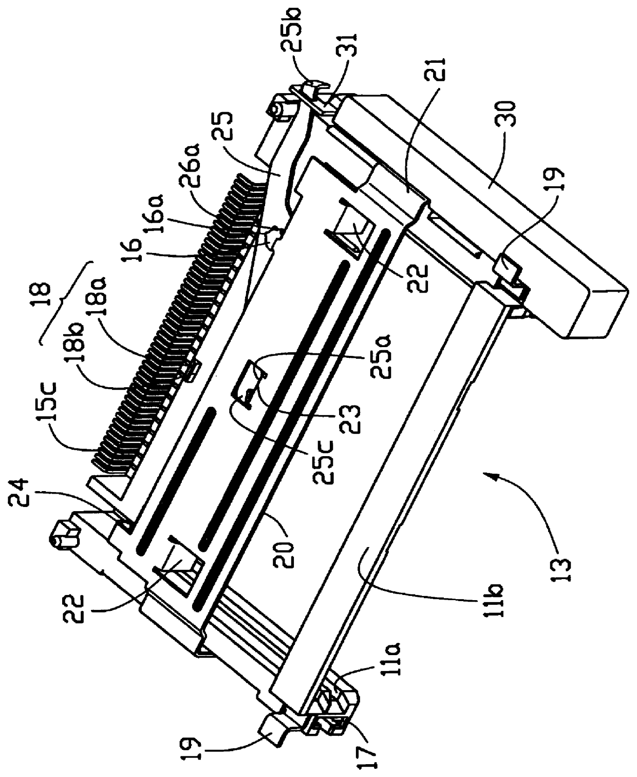
Referring to FIGS. 1 to 5, a compact flash card connector 1 in accordance with the present invention comprises a housing 10 having a pair of guiding arms 11 bridged by a cross bar 12 and defining a receiving space 13 therebetween. The cross bar 12 has a mating face 12a and a rear face 12b opposite to the mating face 12a. The cross bar 12 forms a shaft 16 on a top face thereof. The shaft 16 includes a plurality of projections 16a extending radially from a top edge thereof. The cross bar 12 further forms a stop 18 on the top face thereof. The stop 18 includes an inclined face 18a and a vertical face 18b. An array of passageways 14 is defined between the mating and rear faces 12a, 12b. The cross bar 12 further defines a cutout 12c. The guiding arms 11 are bridged by a reinforced bar 11b.
An array of terminals 15 is assembled in said array of passageways 14 and each terminal 15 includes a base portion 15a fixedly assembled in said passageway 14, a mating portion 15b extending beyond said...
PUM
 Abstract
Description
Claims
Application Information