Spare tire mounting structure

a technology for mounting structures and spare tires, which is applied in the direction of cell components, cell component details, batteries, etc., can solve the problems of moving spare tires that may damage the vehicle body or objects

Active Publication Date: 2020-12-17
HONDA MOTOR CO LTD
View PDF0 Cites 2 Cited by
  • Summary
  • Abstract
  • Description
  • Claims
  • Application Information

AI Technical Summary

Benefits of technology

[0007]In order to achieve the above object, the present invention provides a spare tire mounting structure in which a battery and a spare tire are placed one above the other in a recessed portion of a rear floor of a vehicle body, the spare tire mounting structure including a tire mounting device which is installed on rear frames extending in a front-rear direction along right and left edges of the rear floor, and which mounts the spare tire above the battery housed in the recessed portion. The tire mounting device includes a guard member which restricts forward movement of the spare tire.
[0008]The present invention makes it possible to obtain a spare tire mounting structure capable of suppressing the forward movement of a spare tire due to a rear collision of a vehicle body in a setup where a battery and the spare tire are placed one above the other in a recessed portion of the rear floor of the vehicle body.

Problems solved by technology

In this case, the moved spare tire may damage the vehicle body or objects.

Method used


Image

  • Spare tire mounting structure
  • Spare tire mounting structure
  • Spare tire mounting structure

Examples


embodiment

Structure of Embodiment

[0019]An embodiment of the present invention is described in detail with reference to FIGS. 1 to 10. In the description, the same elements are denoted by the same reference numerals, and redundant description is omitted. In addition, in the figures, “front and rear” indicated by arrows means the front-rear direction of the vehicle body of the automobile (not shown), “right and left” indicated by arrows means the width direction of the vehicle body, and “upper and lower” indicated by arrows means the vertical upper-lower direction.

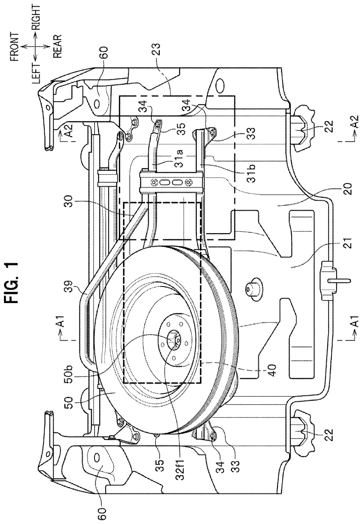
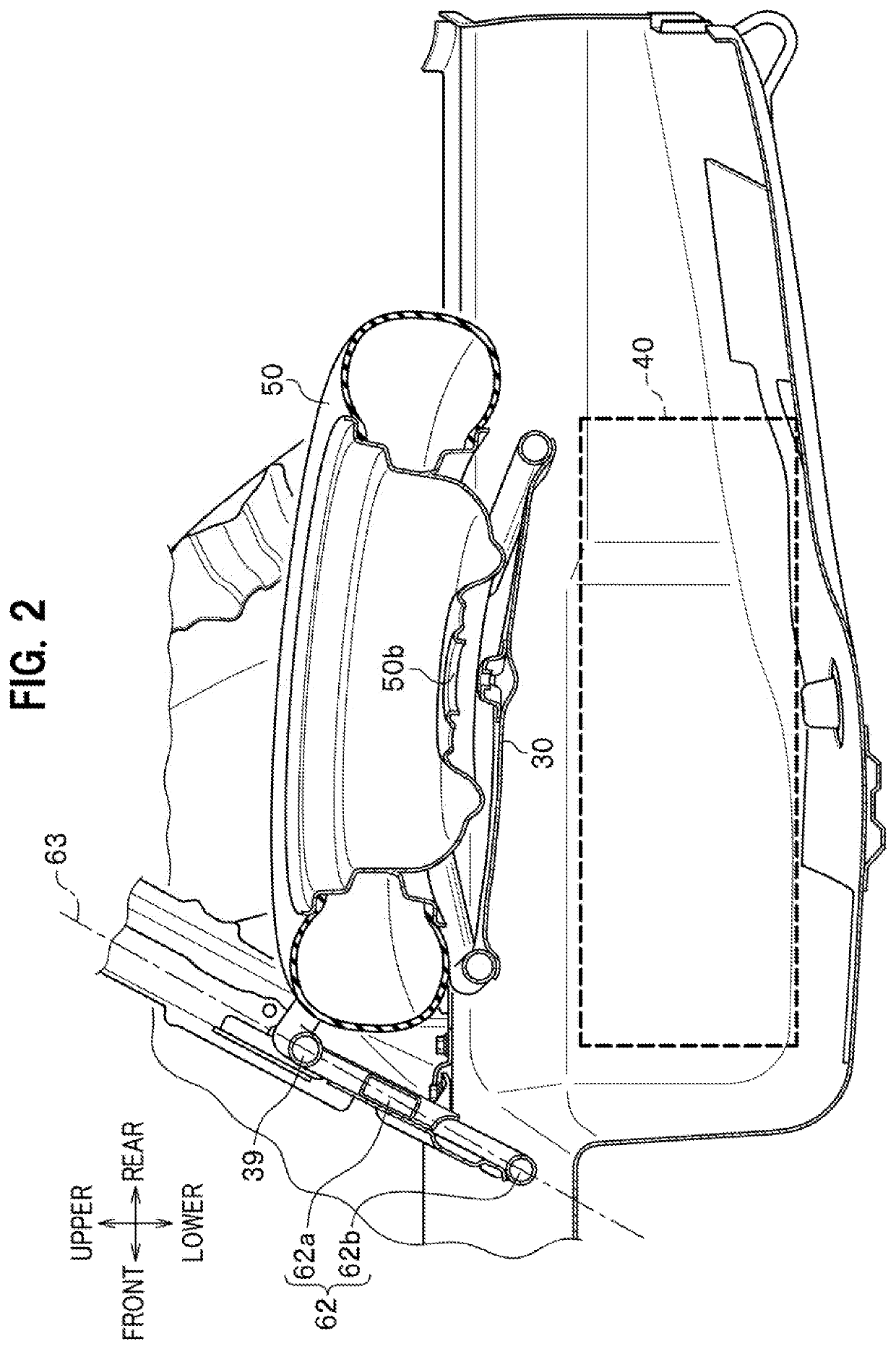
[0020]FIG. 1 is a perspective view showing a spare tire mounting structure in which a battery and a spare tire are placed one above the other in a recessed portion of a rear floor of a vehicle body, and FIG. 2 is a cross-sectional view taken along line A1-A1 of FIG. 1.

[0021]In the spare tire mounting structure 10 shown in FIGS. 1 and 2, right and left rear frames 22 extending in the front-rear direction are arranged along the right an...


PUM

PropertyMeasurementUnit
widthaaaaaaaaaa
distanceaaaaaaaaaa
speedaaaaaaaaaa

Abstract

In a spare tire mounting structure, a tire mounting device extending in a ladder shape and including a guard member on the front side of a vehicle body is installed on right and left rear frames extending in a front-rear direction along right and left edges in a vehicle width direction of a recessed portion of a rear floor of the vehicle body. The guard member has a shape protruded upward. The tire mounting device is installed above a battery placed in the recessed portion of the rear floor. A spare tire is mounted sideways on this tire mounting device.

Description

BACKGROUND OF THE INVENTION1. Field of the Invention[0001]The present invention relates to a spare tire mounting structure in which a battery and a spare tire are placed one above the other in a recessed portion of a rear floor of a vehicle body.2. Description of the Related Art[0002]As a conventional spare tire mounting structure, there is a spare tire mounting structure described in Patent Literature 1, for example. In this structure, a battery is placed in a recessed portion of the rear floor of the vehicle body, and the placed battery is fixed with a T-shaped bracket in a plan view. Moreover, on the fixed battery, a spare tire placed sideways is fixed with another T-shaped bracket.[0003]Since the battery and the spare tire are separately fixed with the respective brackets in this manner, the battery is not detached even when the spare tire is detached due to a rear collision of the vehicle body.PRIOR ART DOCUMENT(S)Patent Literature(s)[0004]Patent Literature 1: JP 2017-132450 AS...

Claims


Application Information

Patent Timeline
Patent Type & Authority Applications(United States)
IPC IPC(8): B62D43/10B60K1/04H01M2/10
CPCB60K2001/0438H01M2/1083B62D43/10B60K1/04B60K2001/045B60K2001/0416H01M2220/20H01M50/249Y02E60/10
Inventor TAKEDA, TOMOYA
Owner HONDA MOTOR CO LTD
Why Eureka
Try Eureka