Seat cushion airbag apparatus
a seat cushion and airbag technology, applied in the direction of pedestrian/occupant safety arrangement, vehicular safety arrangment, vehicle components, etc., can solve the problems of reducing the pelvis receiving performance of the airbag, unable to disclose the structure for installing the airbag, and insufficient performance in restricting forward movement of the lumbar region. , to achieve the effect of restricting forward movement of the lumbar region
- Summary
- Abstract
- Description
- Claims
- Application Information
AI Technical Summary
Benefits of technology
Problems solved by technology
Method used
Image
Examples
first embodiment
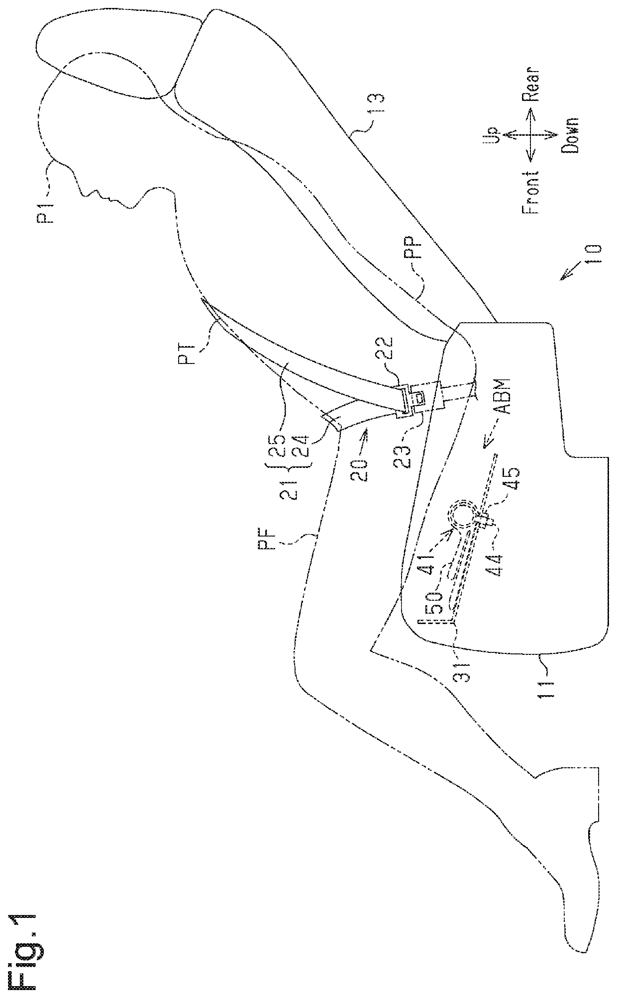
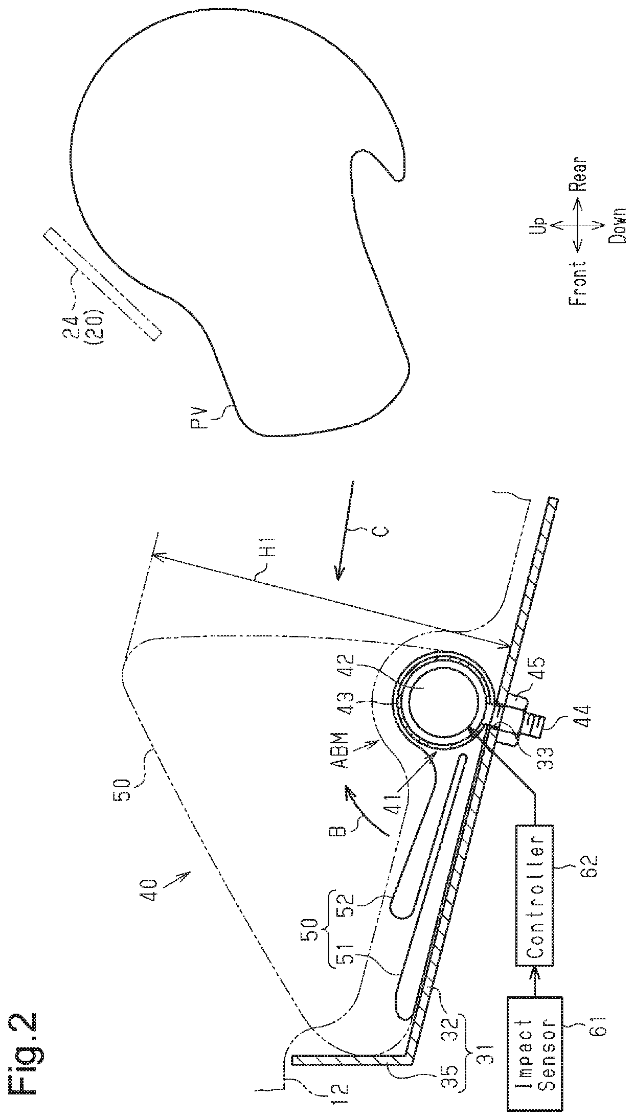
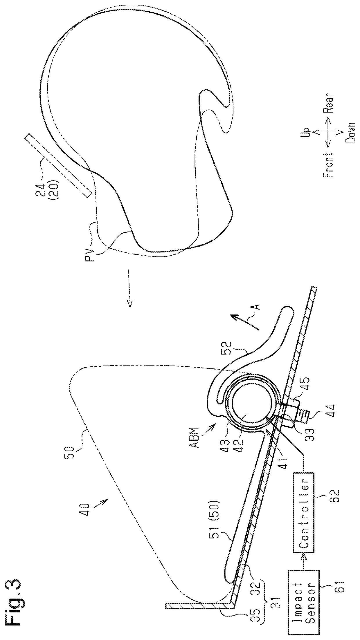
[0022]A vehicle seat cushion airbag apparatus according to a first embodiment will now be described with reference to FIGS. 1 to 3.
[0023]In the following description, the advancing direction of the vehicle is defined as a forward direction. The backward, upward, downward, leftward, and rightward directions are defined with reference to the forward direction. Also, it is assumed that an occupant having a size equivalent to a crash test dummy is seated on the vehicle seat.
[0024]As shown in FIGS. 1 and 2, the vehicle, which is a conveyance, has a vehicle seat 10, which is a conveyance seat for a single person. The vehicle seat 10 includes a seat cushion (seat portion) 11 and a seat back (backrest portion) 13, which extends upward from the rear part of the seat cushion 11. The tilt angle of the seat back 13 is adjustable. The vehicle seat 10 is arranged in the vehicle such that the seat back 13 faces the front of the vehicle. The front-rear direction of the thus arranged vehicle seat 10...
first and second embodiments
Modifications to First and Second Embodiments
[0090]The wall plate portion 35 may be omitted from the support portion 31.
[0091]The fastening portion may be disposed at a position forward of the position in the above-described embodiments (rear end) as long as the fastening portion is located in the region rearward of the center in the front-rear direction of the lower portion of the airbag 50.
[0092]In the first embodiment, the gas generator 41 and the nuts 45 may collectively function as a rear fastening portion as shown in FIG. 5. In this case, in addition to the rear fastening portion, a front fastening portion for fastening the airbag 50 to the support portion 31 may be disposed forward of the rear fastening portion.
[0093]The front fastening portion may be constituted, for example, by a fastener 65 shown in FIG. 5. The fastener 65 includes a plate-shaped holding portion 66, bolts 67, which are orthogonal to and fixed to the holding portion 66, and nuts 68 threaded to the bolts 67....
second embodiment
Modifications to Second Embodiment
[0114]As shown in FIG. 7, two or more band-shaped tethers 56 similar to the one described in the second embodiment may be used. Although two tethers 56 are used in the modification of FIG. 7, three or more tethers 56 may be used. The connecting portions 58 of all the tethers 56 are preferably arranged at a position that is forward of and below the center 55c in the front-rear direction of the tilted surface 55 to ensure the crushed amount of the airbag 50.
[0115]This modification achieves the same operations and advantages as the second embodiment. Furthermore, the connecting portions 58 of the tethers 56 are arranged in a wide region that is forward of and below the center 55c of the tilted surface 55. Thus, when the airbag 50 in the inflated state receives a forward force from the pelvis PV, the tethers 56 restrict forward escape (movement) of a greater region in the airbag 50.
[0116]The multiple tethers 56 may be replaced by a single tether that ha...
PUM
 Abstract
Description
Claims
Application Information
 - R&D
- Intellectual Property
- Life Sciences
- Materials
- Tech Scout
- Unparalleled Data Quality
- Higher Quality Content
- 60% Fewer Hallucinations
Browse by: Latest US Patents, China's latest patents, Technical Efficacy Thesaurus, Application Domain, Technology Topic, Popular Technical Reports.
© 2025 PatSnap. All rights reserved.Legal|Privacy policy|Modern Slavery Act Transparency Statement|Sitemap|About US| Contact US: help@patsnap.com


