Pump and a receptacle fitted therewith

Inactive Publication Date: 2001-03-20
LOREAL SA
View PDF8 Cites 20 Cited by
  • Summary
  • Abstract
  • Description
  • Claims
  • Application Information

AI Technical Summary

Benefits of technology

The present invention seeks to improve the reliability in operation of a pump of the type defined above, i.e. a pump of the type including a moving member mounted to move relative to a support, the moving member having a central duct in which substance to be dispensed penetrates via at least one opening, the support cooperating with the moving member to define, around said central duct, a pump chamber

Problems solved by technology

Nevertheless, that prior art pump does not give entire satisfaction; the Applicant company has observed that

Method used


Image

  • Pump and a receptacle fitted therewith
  • Pump and a receptacle fitted therewith
  • Pump and a receptacle fitted therewith

Examples


Example

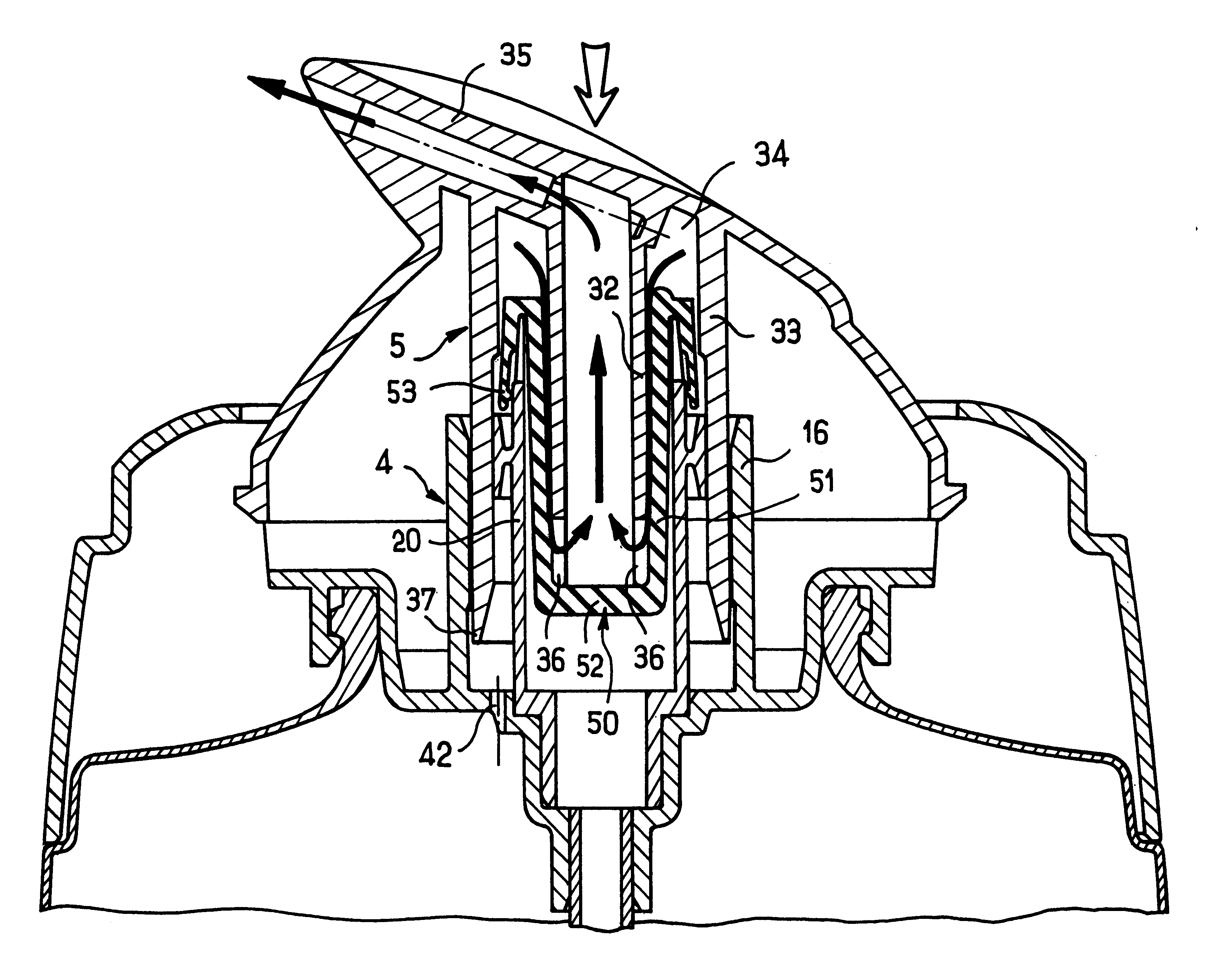
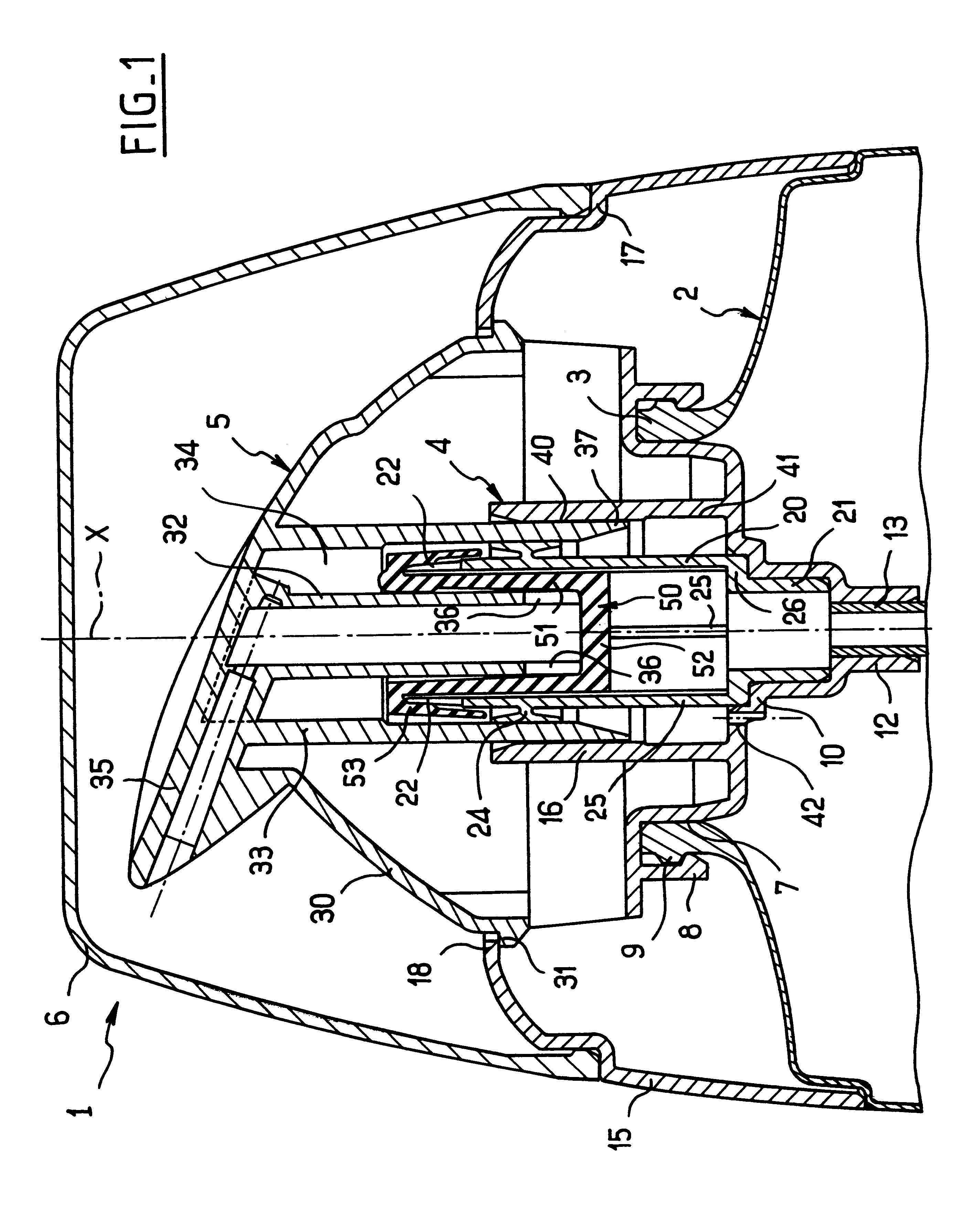
FIG. 1 shows a receptacle 1 having a body 2 forming a tank, with the drawing showing only the top end thereof which has a neck 3 onto which a support 4 is snap-fastened.

The support 4 guides sliding movement of a pushbutton 5 along an axis X, and it serves to receive a removable protective cap 6 that covers the pushbutton 5 prior to first use.

The support 4 has a sealing skirt 7 bearing in leakproof manner against the inside surface of the neck 3.

The sealing skirt 7 is extended radially firstly outwards by fixing tabs 8 snap-fastened onto an annular rim 9 on the neck 3, and secondly inwards by means of a stepped wall 10 defining an endpiece 12 for receiving a dip tube 13 that can be seen in part in the drawing.

An outer skirt 15 and a guide skirt 16 are integrally formed as a molding of plastics material, together with the sealing skirt 7, the fixing tabs 8, and the stepped wall 10.

The outer skirt 15 extends around the neck 3 of the receptacle and has a shoulder 17 on which the protect...


PUM


Abstract

The invention relates to a pump of the type including a moving member mounted to move relative to a support, the moving member having a central duct in which substance to be dispensed penetrates via at least one opening, the support co-operating with the moving member to define, around said central duct, a pump chamber of variable volume, said pump also having a membrane with a central portion in the form of a sleeve that is open at its top end and closed at its bottom end, said central duct being inserted in said central portion, the membrane being organized to isolate the pump chamber from the opening(s) of said central duct while the volume of the pump chamber is increasing and substance is being sucked into it. At least one of the membrane and the central duct is shaped to prevent a leakproof annular zone forming between the membrane and the central duct which would prevent the substance contained in the pump chamber from flowing via said central duct while the volume of the pump chamber is decreasing.

Description

The present invention relates to a pump and to a receptacle fitted with such a pump and containing a liquid, for example a cosmetic cream.French patent 2 728 809 discloses a pump having a pushbutton mounted to move on a support which is secured to the receptacle containing the substance to be dispensed, the pushbutton comprising a circularly-cylindrical central duct having radial openings at its bottom end, the support defining around said duct an annular pump chamber of variable volume. A membrane made out of an elastomer is mounted on the support. The membrane has a circulary-symmetrical central portion in the form of a sleeve that is open at its top end and closed at its bottom end. The central duct of the pushbutton is inserted in the membrane until it bears against the end wall of the sleeve.The membrane thus constitutes a resilient return member enabling the pushbutton to be brought back to its initial position after a quantity of substance has been dispensed.In addition, duri...

Claims


Application Information

Patent Timeline
IPC IPC(8): B05B11/00A45D34/04B65D47/34
CPCB05B11/3001B05B11/3004B05B11/3064B05B11/3076B05B11/3077B05B11/1004B05B11/1001B05B11/1064B05B11/1076B05B11/1077
Inventor BONNINGUE, PHILIPPE
Owner LOREAL SA
Why Eureka
Try Eureka