

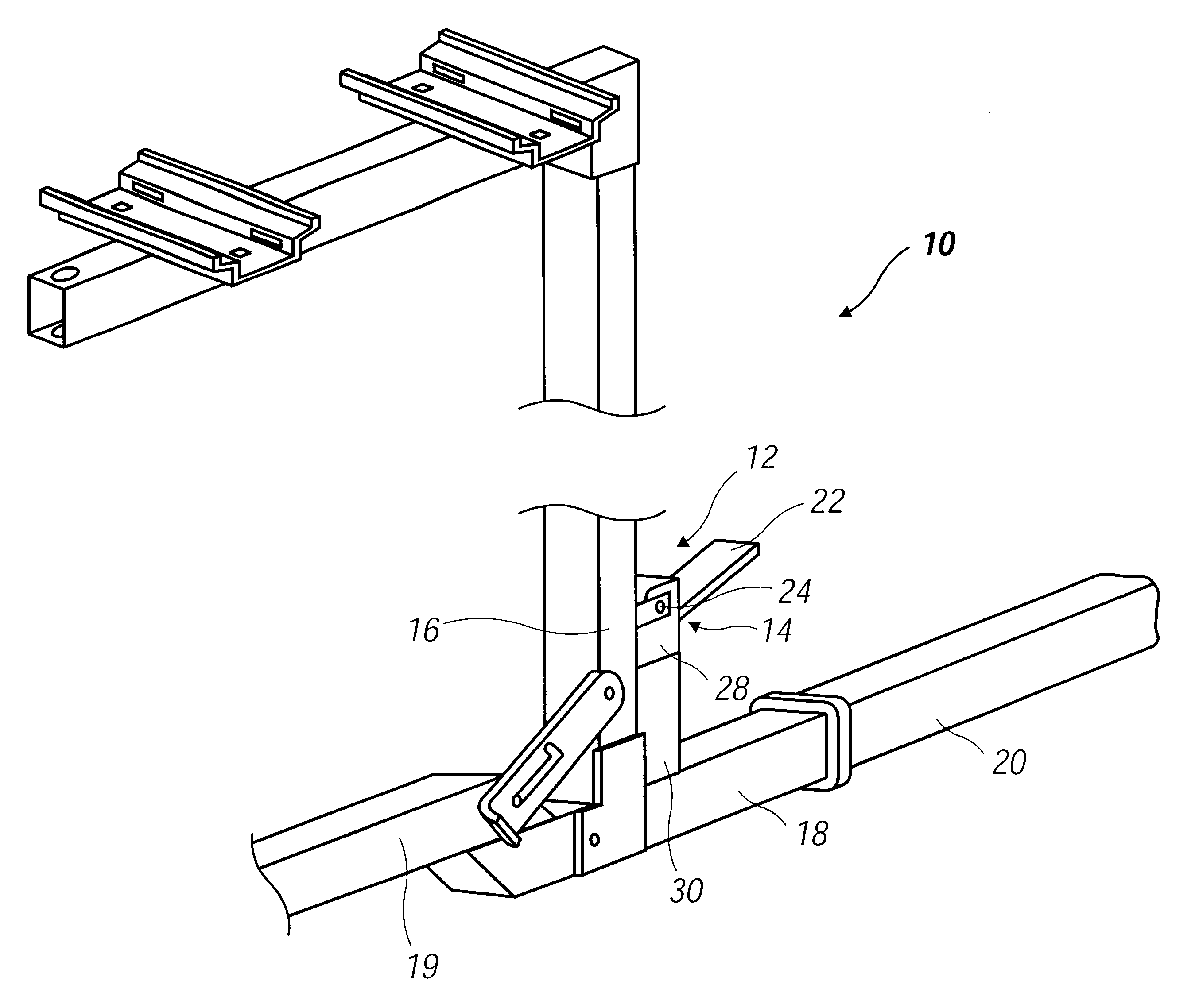
Latching hitch mount carrier
a carrier and hitch technology, applied in the field of carrier frames, can solve the problems of consuming a significant amount of time in properly positioning the normally upright support tube, and affecting the stability of the vehicl
- Summary
- Abstract
- Description
- Claims
- Application Information
AI Technical Summary
Problems solved by technology
Method used
Image

Examples
Embodiment Construction
As required, detailed embodiments of the present invention are disclosed herein; however, it is to be understood that the disclosed embodiments are merely exemplary of the invention that may be embodied in various and alternative forms. The figures are not necessarily to scale, some features may be exaggerated or minimized to show details of particular components. Therefore, specific structural and functional details disclosed herein are not to be interpreted as limiting, but merely as a basis for the claims and as a representative basis for teaching one skilled in the art to variously employ the present invention.
Furthermore, elements may be recited as being "coupled"; this terminology's use contemplates elements being connected together in such a way that there may be other components interstitially located between the specified elements, and that the elements so specified may be connected in fixed or movable relation one to the other.
Referring now to the Figures and using like re...
PUM
 Abstract
Description
Claims
Application Information