Inking unit

Inactive Publication Date: 2002-08-06
HEIDELBERGER DRUCKMASHINEN AG
View PDF16 Cites 15 Cited by
  • Summary
  • Abstract
  • Description
  • Claims
  • Application Information

AI Technical Summary

Problems solved by technology

One problem with such inking units is so-called stenciling, a shadow-like image of a previous part of the printed image, which repeats in the printing direction.
In spite of this, there are many inadequacies that remain, caused by the width and number of ink zones, such as degraded print in the border zones, excess ink feed or insufficient ink feed.
However, ink feed by zones is not possible with a chamber doctor blade ink duct.
A disadvantage of this system is that since braying does not take place, a high level of stenciling occurs.
This makes it unnecessary to have the high degree of braying that is required when lifting an ink strip using an ink lifter.
This means that in conventional inking units, particularly in short

Method used


Image

  • Inking unit
  • Inking unit
  • Inking unit

Examples


Embodiment Construction

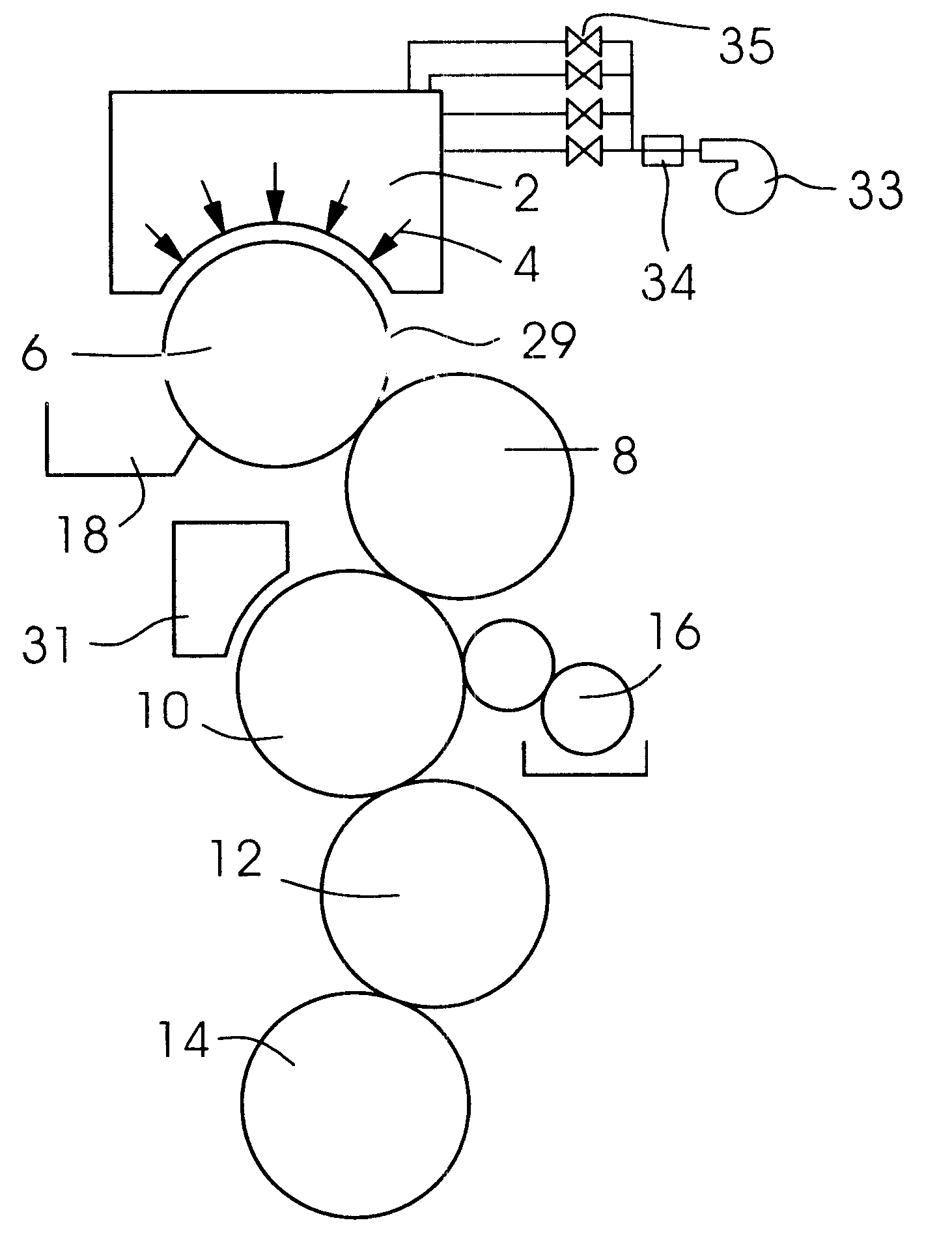
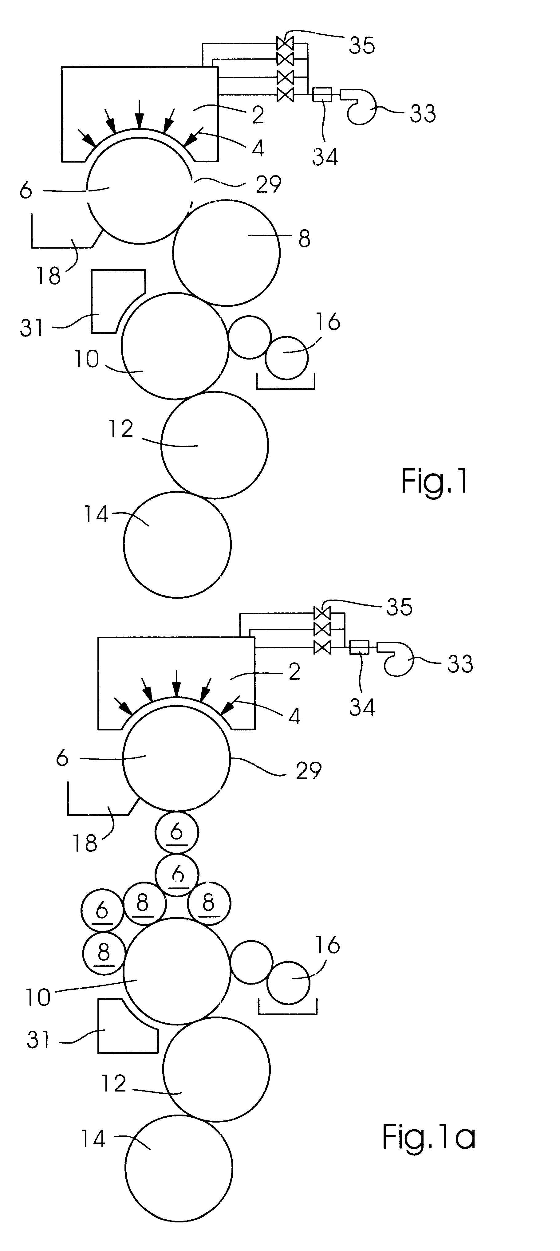
The inking unit shown in FIG. 1 contains an ink jet printing apparatus 2 with a plurality of ink jets 4, which are drawn schematically as arrows, indicating the ink spraying direction. Ink jets 4 are arranged in a two-dimensional matrix which rests against an ink transfer roller 6, forming a slight gap in between. A high-pressure pump device 33 may be provided to supply the ink jet printing apparatus with printing ink at a predetermined high pressure. A heating device 34 to heat the printing ink to a predetermined temperature above room temperature may be provided,and a plurality of valves 35 for selective control of ink feed to the ink jets of the ink jet printing device may be provided.

Ink transfer roller 6 has a rotating mantle surface 29 and rolls on an ink application roller 8, which in turn rolls on a plate cylinder 10 of an offset printing machine. A plate imaging unit 31 is located adjacent to the plate cylinder 10. A blanket cylinder 12 and a printing cylinder 14 are also s...


PUM


Abstract

An inking unit for a printing machine, which includes at least one ink roller rolling on a plate cylinder of the printing machine, an ink jet printing apparatus with a plurality of ink jets that can be controlled selectively, and an ink transfer device with a rotating mantle surface for transferring printing ink from the ink jet printing apparatus to the at least one ink roller. A compact and stencil-free inking unit for high-quality printing is achieved and the at least one ink roller and the ink transfer device, and have the same outside circumference as the plate cylinder.

Description

The invention relates to an inking unit for a printing machine, which includes at least one ink roller rolling on a plate cylinder of the printing machine, an ink jet printing apparatus with a plurality of ink jets that can be controlled selectively, and an ink transfer device with a rotating mantle surface for transferring printing ink from the ink jet printing apparatus to the at least one ink roller.DESCRIPTION OF RELATED ARTInking units with an ink duct as a supply container for printing ink, an ink doctor roller, an ink lifter, and an arrangement of many ink rollers that roll on one another and / or on the plate cylinder of the printing machine, including ink transfer rollers, brayer rollers, and ink application rollers, are frequently used in offset printing machines. The amount of printing ink needed is set by zones, as a function of the print image shape. A resilient blade (doctor blade) is pressed against the doctor roller to a greater or lesser degree, and therefore the amou...

Claims


Application Information

Patent Timeline
IPC IPC(8): B41F31/00B41F31/28B41F31/08B41J2/01
CPCB41F31/28
Inventor SCHMID, GOTTHARD
Owner HEIDELBERGER DRUCKMASHINEN AG
Why Eureka
Try Eureka